Protection circuit for robot control device

Active Publication Date: 2016-09-29
MITSUBISHI ELECTRIC CORP
View PDF4 Cites 2 Cited by
  • Summary
  • Abstract
  • Description
  • Claims
  • Application Information

AI Technical Summary

Benefits of technology

The invention provides a protection circuit for a robot control device that has a simple circuit design but still ensures safety compliance to achieve safety certification.

Problems solved by technology

However, the method (1) has problems such as a purchase price is significantly higher than the power-supply product with no safety certification acquired from the third party.

Method used


Image

  • Protection circuit for robot control device
  • Protection circuit for robot control device
  • Protection circuit for robot control device

Examples


embodiment

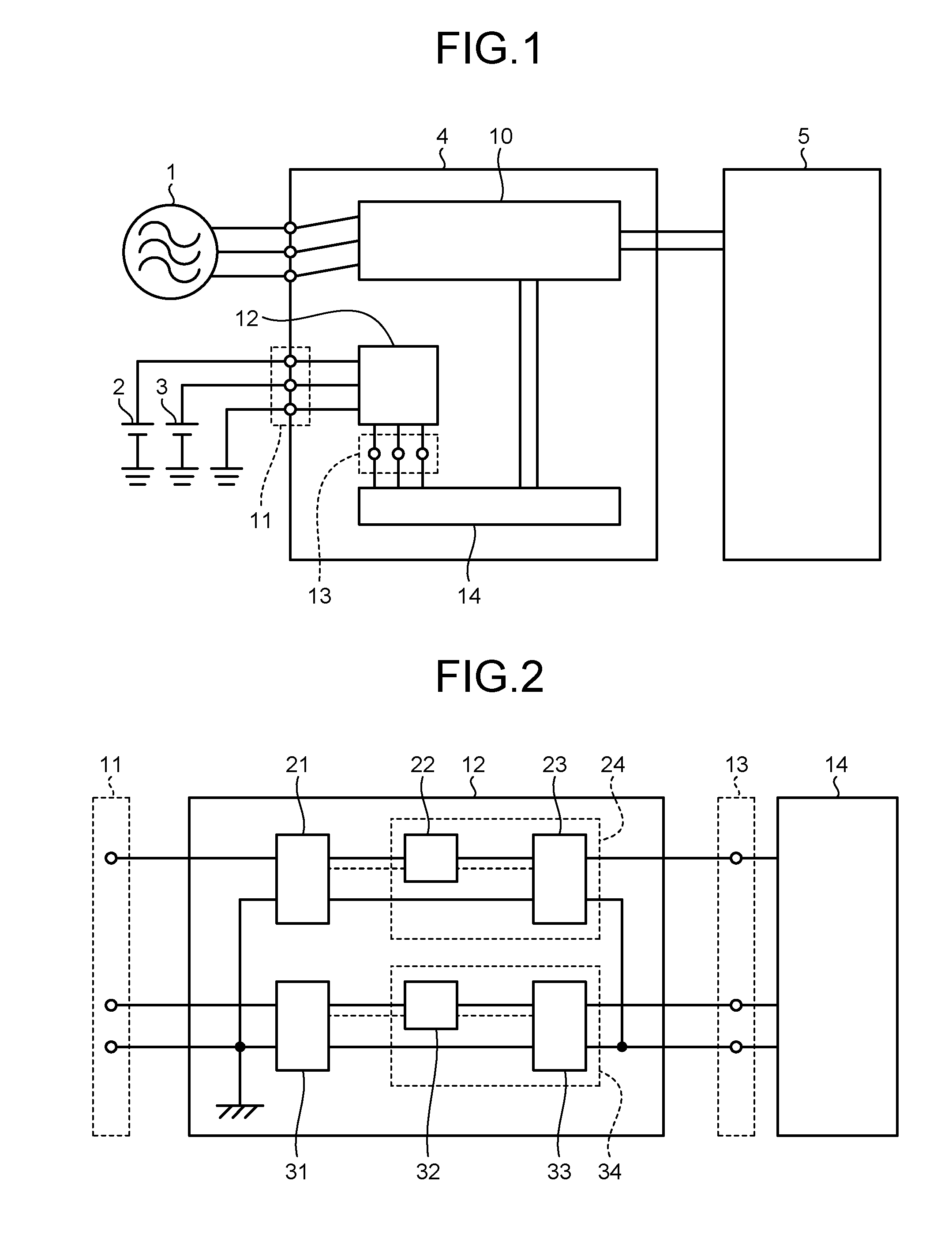
[0021]FIG. 1 is a diagram illustrating a schematic configuration of a robot control device according to an embodiment of the present invention. An AC current is input from an AC power source 1 located outside a control device 4. By using power supplied from the AC power source 1, an AC current for driving a robot 5 that is a load of the control device 4 is generated by a power-conversion circuit portion 10 in the control device 4. The generated AC current is input to the robot 5. Meanwhile, DC currents from DC power sources 2 and 3 located outside the control device 4 are input through a respective power-supply-voltage input terminal 11, and drive a control circuit in a control circuit 14 in the control device 4.

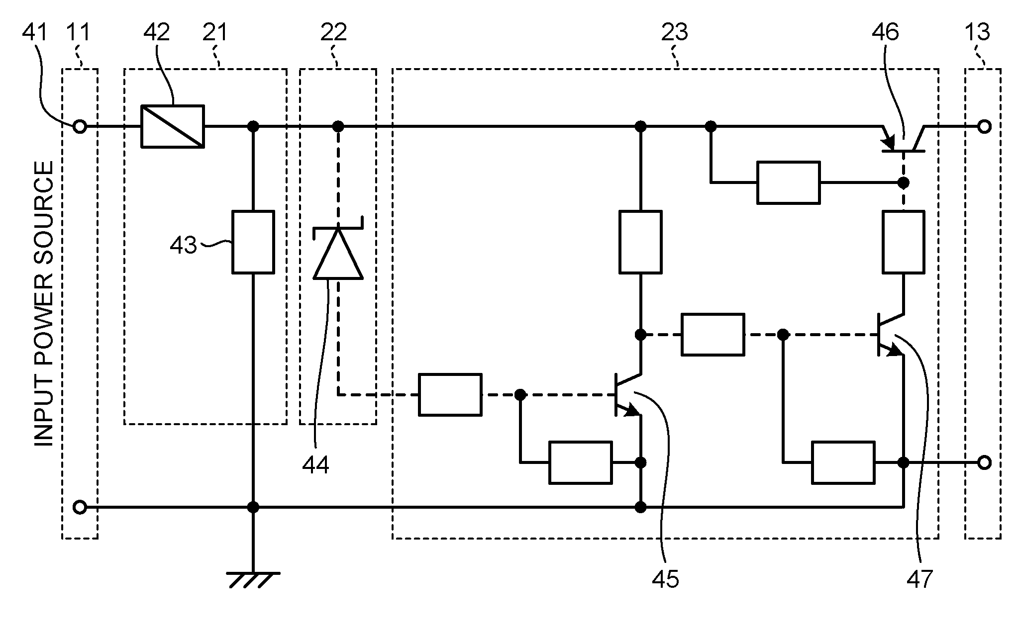
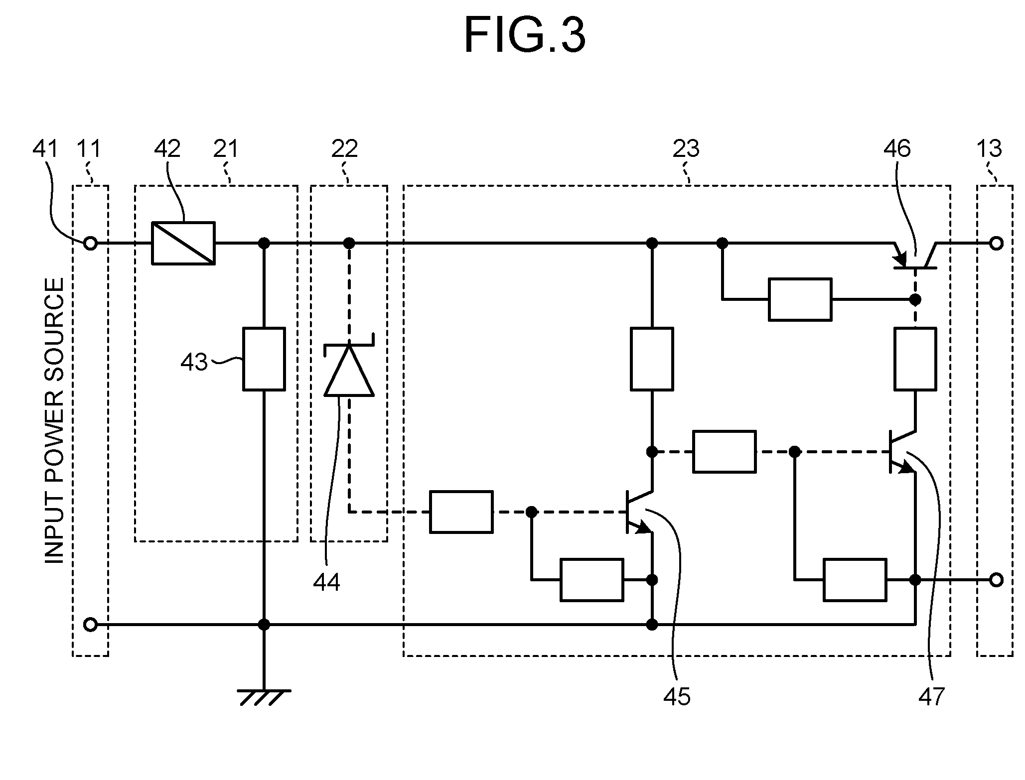
[0022]An overvoltage-protection circuit 12 constituting a protection circuit of the robot control device according to the present embodiment is disposed between the DC power sources 2 and 3 and the control circuit 14. In a case where a voltage value of a voltage applied from...


PUM


Abstract

A first current cut-off unit that cuts off a current input from a power-supply-voltage input terminal connected to an AC power source when a current value of the current exceeds a preset threshold, and a second current cut-off unit that cuts off a current output from the first current cut-off unit when a voltage value of a voltage applied from the power-supply-voltage input terminal exceeds a preset threshold are configured. A current cut-off element provided on a current path from the power-supply-voltage input terminal toward a DC output terminal, and a resistor that draws a current having passed through the current cut-off element toward a ground are provided as the first current cut-off unit.

Description

FIELD[0001]The present invention relates to a protection circuit for a robot control device.BACKGROUND[0002]A robot control device for controlling a robot is required to comply with various safety standards. A countermeasure against overvoltage failures of an input power source is one of the requirements.[0003]Conventionally, as an overvoltage protection countermeasure applied to a power-supply circuit for complying with the safety standards, one of following methods is adopted:[0004](1) A power-supply product with a safety certification acquired from a third-party organization is used; and[0005](2) A power-supply product with no safety certification acquired from a third-party is adopted and an overvoltage protection function is added to the power-supply product later.[0006]Out of the above methods, the method (1) is easy as a measure for achieving the overvoltage protection countermeasure. However, the method (1) has problems such as a purchase price is significantly higher than t...

Claims


Application Information

Patent Timeline
IPC IPC(8): H02H7/20H02H3/38
CPCH02H3/38H02H7/20H02H3/08H02H3/20B25J19/06H02J1/00
Inventor ISHIKAWA, TAKAFUMI
Owner MITSUBISHI ELECTRIC CORP
Why Eureka
Try Eureka