
Substrate processing apparatus

a processing apparatus and substrate technology, applied in conveyors, chemical vapor deposition coatings, coatings, etc., can solve the problems of difficult localization, difficult to locate, and the sub-bodies of the (re)moved upper tunnel may not seamlessly fit back into place before the entire process tunnel

Active Publication Date: 2016-09-29
ASM INTERNATIONAL
View PDF53 Cites 16 Cited by
  • Summary
  • Abstract
  • Description
  • Claims
  • Application Information

AI Technical Summary

Benefits of technology

This patent text describes an improved version of a substrate processing apparatus that allows easier access to the process tunnel space to address any problems that arise. The lower tunnel body has two lateral tunnel walls, which help prevent substrates from sliding or floating out. The contactless transport of double-floatingly supported substrates through the process tunnel is crucial for stable operation. The design also minimizes leakage of process gases through leaks between the tunnel bodies, which could contaminate the environment or affect the health of employees. An external gas exhaust conduit is connected to a gas exhaust channel in a lateral tunnel wall to prevent uncontrolled pressure variations and facilitate a fluid-tight connection.

Problems solved by technology

The congestion, however, may be difficult to localize, and may not be confined to a single location in the process tunnel.
Furthermore, in particular when heated gases are used for the gas bearings, (re)moving one or more upper tunnel sub-bodies may cause them to cool at a different rate than the remaining upper tunnel sub-bodies (which, conversely, may be given room to expand), as a result of which the (re)moved upper tunnel sub-bodies may not seamlessly fit back into place before the entire process tunnel has cooled down.

Method used


Image

  • Substrate processing apparatus
  • Substrate processing apparatus
  • Substrate processing apparatus

Examples


Embodiment Construction

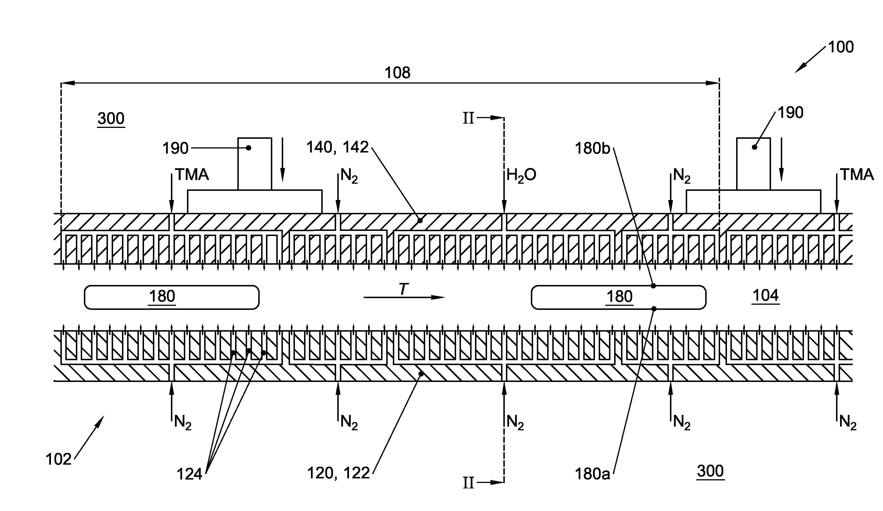
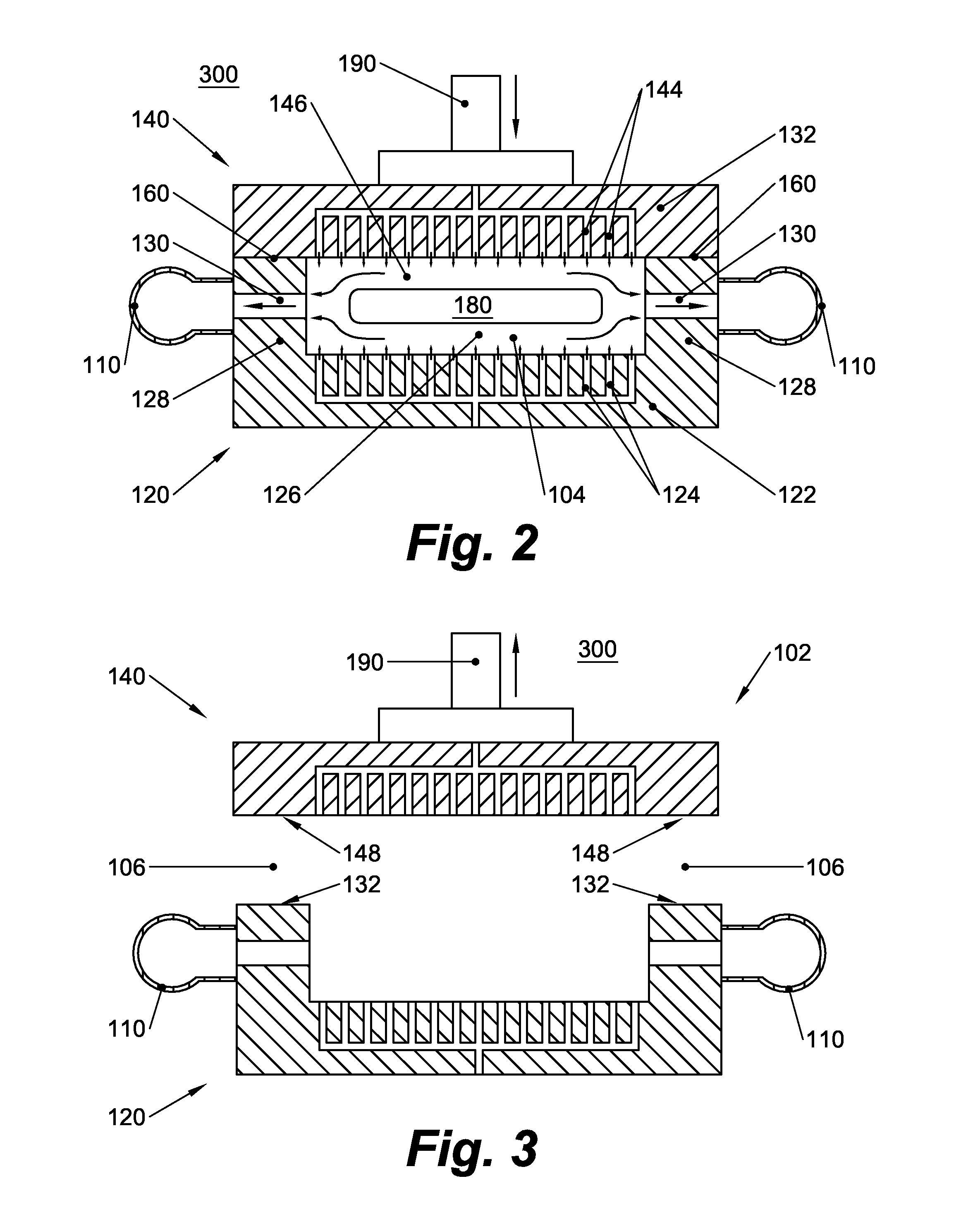
[0028]Below, a basic exemplary embodiment of a substrate processing apparatus according to the present disclosure is described with reference to FIGS. 1-3. The exemplary embodiment is set up as a spatial atomic layer deposition (ALD) apparatus. It is understood, however, that the scope of application of the apparatus is not limited to the field of atomic layer deposition. The apparatus may alternatively be applied for the purpose of performing other substrate processing treatments, such as annealing.

[0029]Referring now to FIGS. 1-3. The disclosed apparatus 100 may include a typically linear or straight process tunnel 102 through which a substrate 180, e.g. a silicon wafer, preferably as part of a train of substrates, may be conveyed in a uni-directional or bi-directional manner. That is, the substrate 180 may be inserted into the process tunnel 102 at an entrance thereof, and be uni-directionally conveyed to an exit. Alternatively, the process tunnel 102 may have a dead end and the ...


PUM

PropertyMeasurementUnit
Forceaaaaaaaaaa
Pressureaaaaaaaaaa
Pressure dropaaaaaaaaaa

Abstract

A substrate processing apparatus (100) comprising a process tunnel (102) including a lower tunnel wall (122), an upper tunnel wall (142), and two lateral tunnel walls (128), said tunnel walls being configured to bound a process tunnel space (104) that extends in a longitudinal transport direction (7) and that is suitable for accommodating at least one substantially planar substrate (180) oriented parallel to the upper and lower tunnel walls (122, 142), the process tunnel being divided in a lower tunnel body (120) comprising the lower tunnel wall and an upper tunnel body (140) comprising the upper tunnel wall, which tunnel bodies (120, 140) are separably joinable to each other along at least one longitudinally extending join (160), such that they are mutually movable between a closed configuration in which the tunnel walls (122, 128, 42) bound the process tunnel space (104) and an open configuration that enables lateral maintenance access to an interior of the process tunnel.

Description

FIELD OF THE INVENTION[0001]The present invention relates to a high-throughput substrate processing apparatus for processing double-floatingly supported substrates during transport through a process tunnel.BACKGROUND[0002]International patent application publication WO 2011 / 062490 in the name of Levitech B.V. discloses a substrate processing apparatus including a process tunnel through which semiconductor substrates may be contactlessly advanced in rapid succession while being subjected to a variety of treatments such as, for example, spatial atomic layer deposition (ALD) and annealing. A problem addressed in WO'490 is that the substrates, which are floatingly supported between an upper and lower gas bearing, may become destabilized by gas flows necessary to maintain the gas bearings. Consequently, the substrates may stray from their predetermined trajectory towards the edges of the gas bearings and / or undergo angular displacements, as a result of which they may collide with and / or ...

Claims


Application Information

Patent Timeline
IPC IPC(8): C23C16/455C23C16/44H01L21/677
CPCC23C16/45544C23C16/4412H01L21/67784B65G51/03C23C16/45551C23C16/45557C23C16/54
Inventor GRANNEMAN, ERNST HENDRIK AUGUSTTAK, PIETER
Owner ASM INTERNATIONAL
Learn More