Method for manufacturing wire harness, wire harness manufacturing device, wire harness, and retention component

a manufacturing device and wire harness technology, applied in the direction of electric/fluid circuits, coatings, transportation and packaging, etc., can solve the problems of manual labor of winding and tying the belt, and achieve the effects of improving work efficiency, reducing temperature, and reducing the temperatur

Active Publication Date: 2016-09-29
DAIWA KASEI IND CO LTD +1
View PDF0 Cites 0 Cited by
  • Summary
  • Abstract
  • Description
  • Claims
  • Application Information

AI Technical Summary

Benefits of technology

[0011]With this invention, since molding of the retention portion and a tying operation of tying the wiring bundle can be conducted simultaneously, the conventional tying operation performed by hands of a worker can be omitted, and working efficiency can be improved significantly. In addition, with this invention, since loading of the resin starts from the engagement portion-molding space having a complicated shape, the resin reaches the very tip of the engagement portion-molding space with certainty. In addition, the outer circumferential surface of the wiring bundle is rugged. Thus, the resin loaded within the retention portion-molding space may leak outside from concavities on the outer circumferential surface of the wiring bundle. However, with this invention, since the inflow opening for the resin exists on the engagement portion-molding space, the engagement portion-molding space is loaded first, and then the resin reaches the retention portion-molding space. Since the resin, which has reached the retention portion-molding space, has a lower temperature, a higher viscosity, and a lower pressure; the resin is unlikely to leak outside from inter-wire gaps that form the concavities. This is convenient also from a standpoint of preventing leakages. In addition, reduction of pressure in the resin, which has reached the retention portion-molding space, means lower force that tries to push the wiring bundle, located at the center of the annular retention portion-molding space, out from the center, and is convenient also from a standpoint of being able to mold the annular retention portion with certainty.

Problems solved by technology

However, with the belt clamp of Japanese Laid-Open Patent Publication No. 2005-341776, a manual labor of winding and tying the belt to the wiring bundle forming the wire harness is required.

Method used


Image

  • Method for manufacturing wire harness, wire harness manufacturing device, wire harness, and retention component
  • Method for manufacturing wire harness, wire harness manufacturing device, wire harness, and retention component
  • Method for manufacturing wire harness, wire harness manufacturing device, wire harness, and retention component

Examples


Embodiment Construction

[0035]In the following, embodiments of this invention will be described with reference to the examples shown in the drawings.

[0036]As shown in FIGS. 1 and 2, a retention component 10 of this embodiment is formed of a resin molded body that integrally includes an engagement portion 11 to be attached to a vehicle body, and a retention portion 12 configured to retain a wiring bundle 50 formed of multiple wiring members 5. A wire harness 1 has the retention component 10, and the wiring bundle 50 retained in a closely adhered state by the retention portion 12 of the retention component 10. The wiring members 5 are those that are known in the art, including an electrically conductive core wire formed of one or more lead wires, and an electrically non-conductive cover portion configured to cover the outer circumference of the core wire.

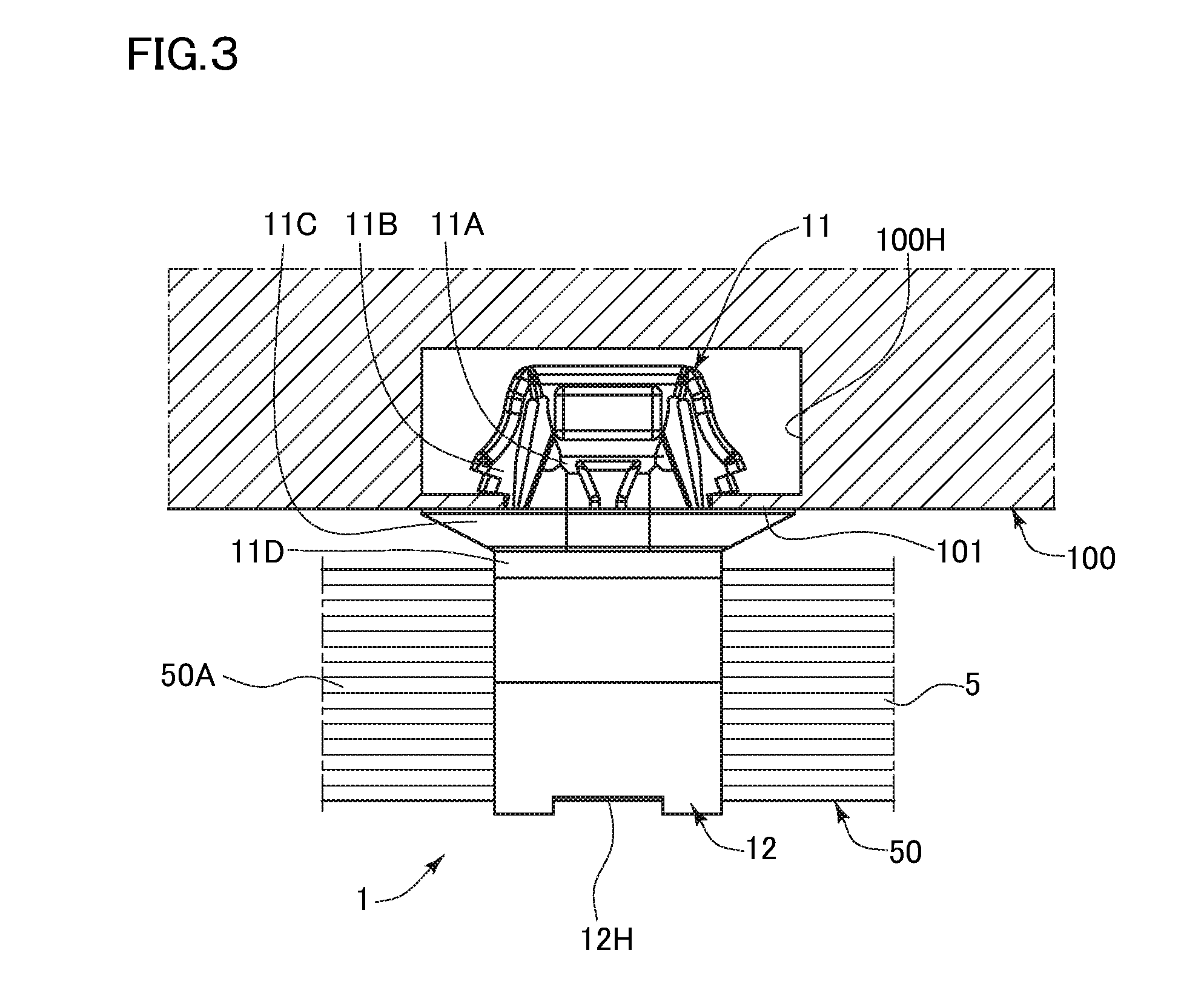
[0037]As shown in FIG. 3, the engagement portion 11 is a part that is to be attached to a vehicle body 100 side when the engagement portion 11 is inserted i...


PUM

PropertyMeasurementUnit
thermal conductivityaaaaaaaaaa
lengthaaaaaaaaaa
circumferenceaaaaaaaaaa

Abstract

An objective is to provide a hitherto not-existing retention component that is for a wiring bundle and can be manufactured without tying the wiring bundle, a wire harness including the retention component, and a manufacturing method and a manufacturing device for the wire harness.
A metal mold that is used has a penetration hole in which a wiring bundle is to be penetratingly disposed, an annular retention portion-molding space for surrounding the outer circumference of the wiring bundle, and an engagement portion-molding space communicatively connected with the retention portion-molding space. The wiring bundle is disposed in the penetration hole, a melt resin is poured in the retention portion-molding space from the engagement portion-molding space, and solidified through cooling to mold a retention portion integrally with a engagement portion in a state of being closely adhered to an outer circumference of the wiring bundle.

Description

RELATED APPLICATIONS[0001]This application claims the priority of Japanese Patent Application No. 2015-063143 filed on Mar. 25, 2015 and 2016-036240 filed on Feb. 26, 2016. The disclosure of the prior application is hereby incorporated herein in the entirety by reference.BACKGROUND OF THE INVENTION[0002]1. Field of the Invention[0003]This invention relates to a retention component for a wiring bundle, a wire harness including the retention component, and a manufacturing method and manufacturing device for the wire harness.[0004]2. Description of Related Art[0005]For example, in a vehicle, attachment objects such as a wire harness are laid in a vehicle body. In this case, a wiring bundle forming the wire harness is tied and retained by a retention component, and the retention component is attached to the vehicle body. Examples of such a retention component include a so-called belt clamp or the like for tying the wiring bundle with a belt (see Japanese Laid-Open Patent Publication No....

Claims


Application Information

Patent Timeline
Patent Type & Authority Applications(United States)
IPC IPC(8): B05D1/26B60R16/02
CPCB05D1/265B05D2256/00B60R16/0215B60R16/0207B29C39/10B29C45/00B29C45/14016B29C45/14065B29C45/14262B29C45/14385B29C45/14467B29C45/14549H02G3/32
Inventor KAMIYA, KOUJIITO, YUUSUKESUZUKI, MAKOTOSUZUKI, HIROAKIFURUKI, KENTAROICHIHARA, MASANARI
Owner DAIWA KASEI IND CO LTD
Why Eureka
Try Eureka