Temperature measurement system employing an electromagnetic transponder and separate impedance-changing parasitic antenna

a technology of parasitic antenna and electromagnetic transponder, which is applied in the field of temperature sensors and temperature measurement systems, can solve the problems of difficult injection molding of the physical connection between the tags and switches is inherently delicate, and the difficulty of integrating such a tag/switch combination within an object whose temperature is difficult to achieve, so as to prevent any substantial lateral movement of the dome and rapid heating of the dome

Active Publication Date: 2016-09-22
TSI TECHNOLOCIES LLC
View PDF3 Cites 5 Cited by
  • Summary
  • Abstract
  • Description
  • Claims
  • Application Information

AI Technical Summary

Benefits of technology

The present invention provides better wireless temperature sensors that can be used on a variety of objects, including food servingware. These sensors eliminate the need for physical or wired connections between the sensor and a temperature-sensitive switch. The sensors have a fixed position, which can be achieved by mounting them on a rigid or flexible substrate. The substrate should be insulating and able to withstand the temperatures to which the object will be exposed. The sensors can be easily integrated into objects, including through injection molding.

Problems solved by technology

There are several disadvantages with the tag / switch combination and associated measurement system of the '169 patent.
First, the tag / switch combination is difficult to incorporate within an object whose temperature is to be measured.
The physical connection between the tags and switches is inherently delicate, making use of fine connection wires and connectors soldered or affixed to the tag.
As such, it is very difficult to injection mold such a tag / switch combination within an object.
Second, if the connection between the switch and tag is short in length so as to facilitate manufacturing, the tag may be too close to the object to be measured to allow for good communication with the tag, owing to antenna de-tuning by the object, especially if the object is made from an electrically conducting material.
Conversely, if the connections are lengthened so as to enhance communications by eliminating any adverse effects from the object, the difficulty of incorporation into the object increases.
Third, the fact that the tag is connected to the switch means that thermal energy from the object in contact with the switch will conduct or radiate to the tag, either through the connecting leads or simply by conduction through adjacent matter.
Thus, should the tag / switch combination be used to measure high object temperatures, the integrated circuitry of the tag may be destroyed or tag communication may be disrupted.
However, the transponder system of the '608 patent is not designed to measure object temperatures, either at single or multiple temperature measurement locations on an object.

Method used


Image

  • Temperature measurement system employing an electromagnetic transponder and separate impedance-changing parasitic antenna
  • Temperature measurement system employing an electromagnetic transponder and separate impedance-changing parasitic antenna
  • Temperature measurement system employing an electromagnetic transponder and separate impedance-changing parasitic antenna

Examples


Embodiment Construction

Temperature Measurement Systems

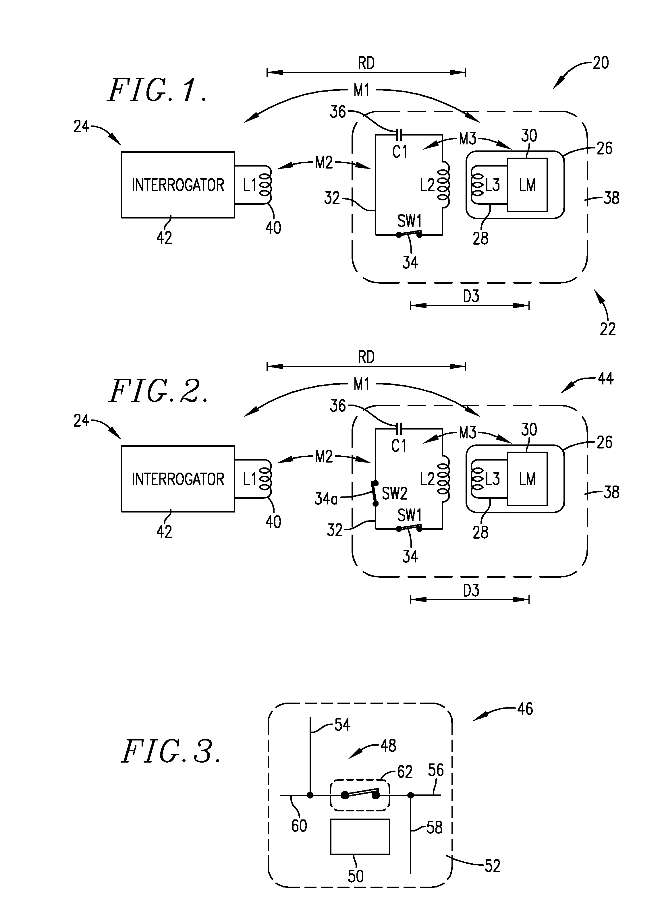
[0029]Turning now to the drawings, FIG. 1, an exemplary temperature measurement system 20 is illustrated, which broadly includes a temperature sensor 22 and an interrogator 24. The sensor 22 is designed to be placed in effective thermal contact with an object whose temperature is to be sensed, whereas the interrogator 24 is a separate component in proximity to the sensor 22.

[0030]The preferred sensor 22 includes a transponder, here in the form of RFID tag 26, advantageously a UHF Tagsys AK5, which has the ability to be read and written, with 160 reprogrammable bits and 96 identification bits. The tag 26 has an antenna 28 of self-inductance L3 and a microcircuit 30 (labeled LM) coupled with antenna 28 and operable to extract energy from the antenna and to generate and convey a reply signal to the antenna 28, or alternately to another antenna (not shown). Additionally, the sensor 22 has a separate parasitic antenna 32 having a characteristic impedance va...


PUM


Abstract

Temperature measurement systems (20) include a temperature sensor (22) and an electronic signal interrogator (24). The temperature sensor (22) has a transponder (26) equipped with an antenna (28), and a separate parasitic antenna (32) with a temperature-sensitive transducer (34, 68-74, 78a-84a), while the interrogator (24) has a transmitter (42) and antenna (40). The sensor (22) is designed to be placed in thermal contact with an object to be temperature-measured, with the interrogator (24) placed in proximity to the object. The systems (20) may be used with food servingware domes (88, 114), which can be preheated and placed over a food-bearing plate to maintain the temperature of the food.

Description

CROSS-REFERENCE TO RELATED APPLICATION[0001]This application claims the benefit of identically-titled provisional application Ser. No. 62 / 134,246, filed Mar. 17, 2015, which is incorporated by reference herein in its entirety.BACKGROUND OF THE INVENTION[0002]1. Field of the Invention[0003]The present invention is broadly concerned with temperature sensors and temperature measurement systems permitting wireless temperature measurement of various objects during heating or cooling thereof. More particularly, the invention is concerned with such sensor and systems, and especially those designed for heating of food servingware, such as food plate domes. The sensors include a transponder and a proximal parasitic antenna, the latter having a temperature-sensitive transducer operable to change the impedance value of the parasitic antenna when the object being temperature-sensed reaches a predetermined temperature for transducer operation.[0004]2. Description of the Prior Art[0005]Remote, wi...

Claims


Application Information

Patent Timeline
IPC IPC(8): H05B6/06H05B6/12G01K7/36H01Q1/44G01K1/02
CPCH05B6/062H01Q1/44H05B6/1209G01K7/36G01K1/024H05B6/105H05B2213/06H05B2213/07
Inventor BOURKE, III, MICHAEL J.CLOTHIER, BRIAN L.
Owner TSI TECHNOLOCIES LLC
Why Eureka
Try Eureka