
Improved storage and charging station system for portable electronic devices

a technology for electronic devices and charging stations, applied in the field of storage and charging systems for electronic devices, can solve the problems of inability of business or medical service providers to control portable electronic devices, difficulty in maintaining portable electronic devices, and difficulty in charging or recharging devices during the day, so as to facilitate charging or recharging of devices, reduce the amount of space consumed, and reduce the visibility and entanglement of associated cables.

Active Publication Date: 2016-09-22
ROBERTS NATHAN R
View PDF31 Cites 20 Cited by
  • Summary
  • Abstract
  • Description
  • Claims
  • Application Information

AI Technical Summary

Benefits of technology

The present invention is a storage system for portable electronic devices that allows for easy charging and storage of multiple devices while minimizing space consumption. The system is expandable and has a unique design that allows easy identification of content. The system also includes a cable management system for centralized charging and data distribution, as well as a locking assembly for theft reduction. Overall, the system provides a central location for storage, inventory, and identification of portable electronic devices, assisting with the deployment, management, and theft reduction of large numbers of portable electronic devices.

Problems solved by technology

In both of these examples, while utilizing the portable electronic devices as an educational tool is an outstanding way for students to learn, it can lead to issues in maintaining the portable electronic devices.
For example, it may be difficult to inventory the devices during the day, charge or recharge the devices, account for the return of all devices once students complete use of the devices, and / or efficiently deploy new software or associated updates.
Again, many of the same problems as would arise in an educational setting, such as the ability to inventory or account for the return of all devices may arise at these public settings.
The inability of the business or medical service provider to control the portable electronic devices can interrupt any efficiency or operational gains.
For example, should an employee take a portable electronic device from the premises and forget to return it, that employee will not be able to use the portable electronic device during performance of his or her job.
Similarly, if an employee fails to charge or recharge the battery of the portable electronic device, the portable electronic device can run out of power during an employee's work day, rendering the portable electronic device useless.
As another example, should an employee remove the portable electronic device from the premises, the information stored on the electronic device may be misappropriated.
This and other situations not referenced can lead to inefficiencies and unnecessary risks of loss.
In addition, these employees may require daily travel in the performance of their job responsibilities.
Again, many of the same problems as recited above, such as forgetting, misplacing, losing, or failing to fully recharge portable electronic devices, or the failure of employees to properly maintain the portable electronic devices, may lead to interruption of efficiency, loss of operational gains, and / or unnecessary risk of loss.
For example, it can be difficult for the sports team to easily and efficiently update game planning materials.
Accordingly, it can be difficult to quickly and efficiently distribute updated game preparation materials to the portable electronic devices assigned to each of the players.

Method used


Image

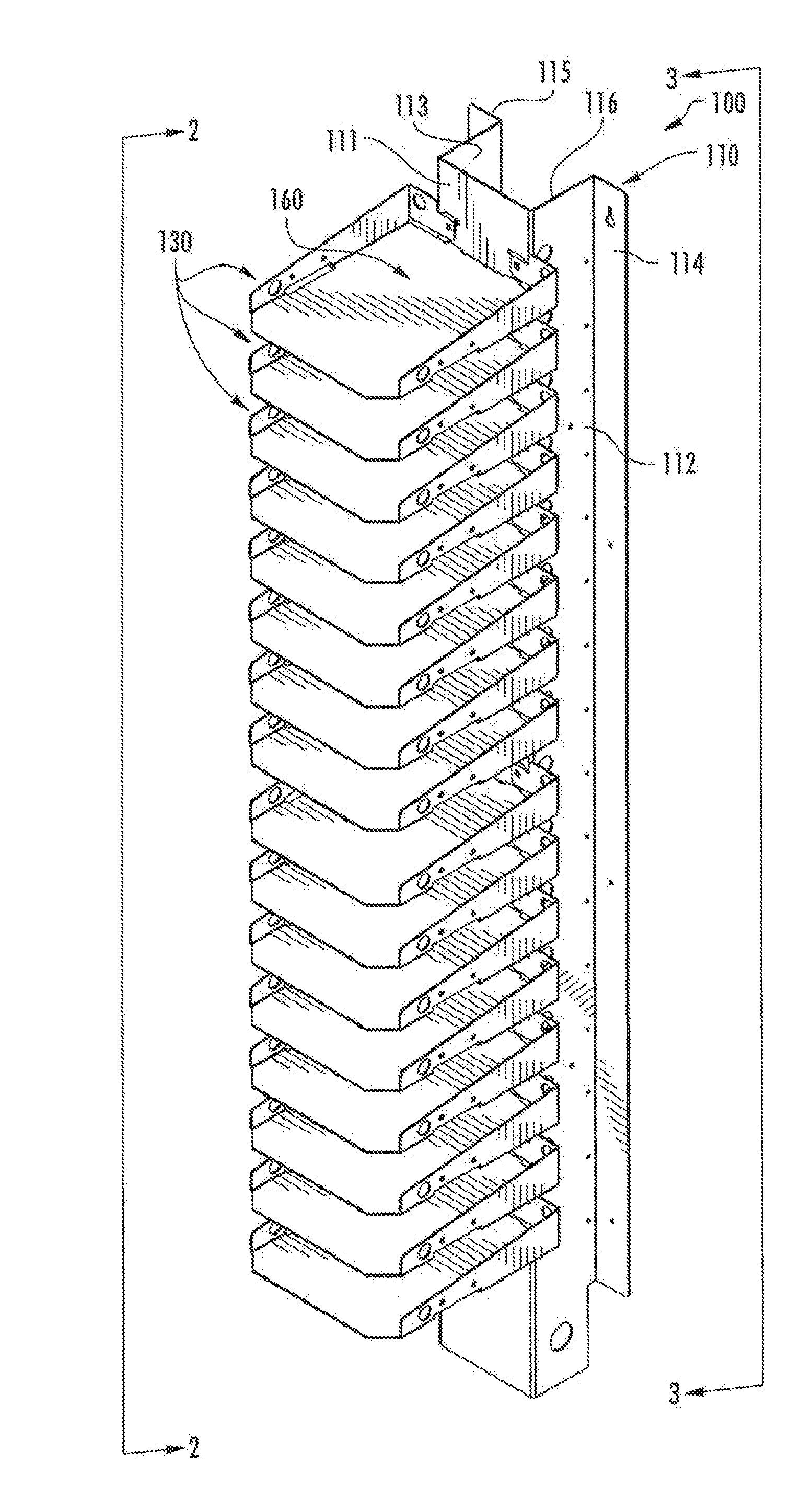
  • Improved storage and charging station system for portable electronic devices
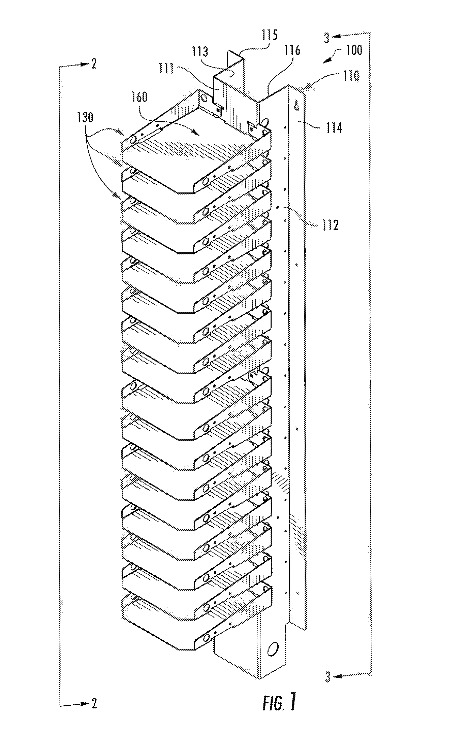
  • Improved storage and charging station system for portable electronic devices
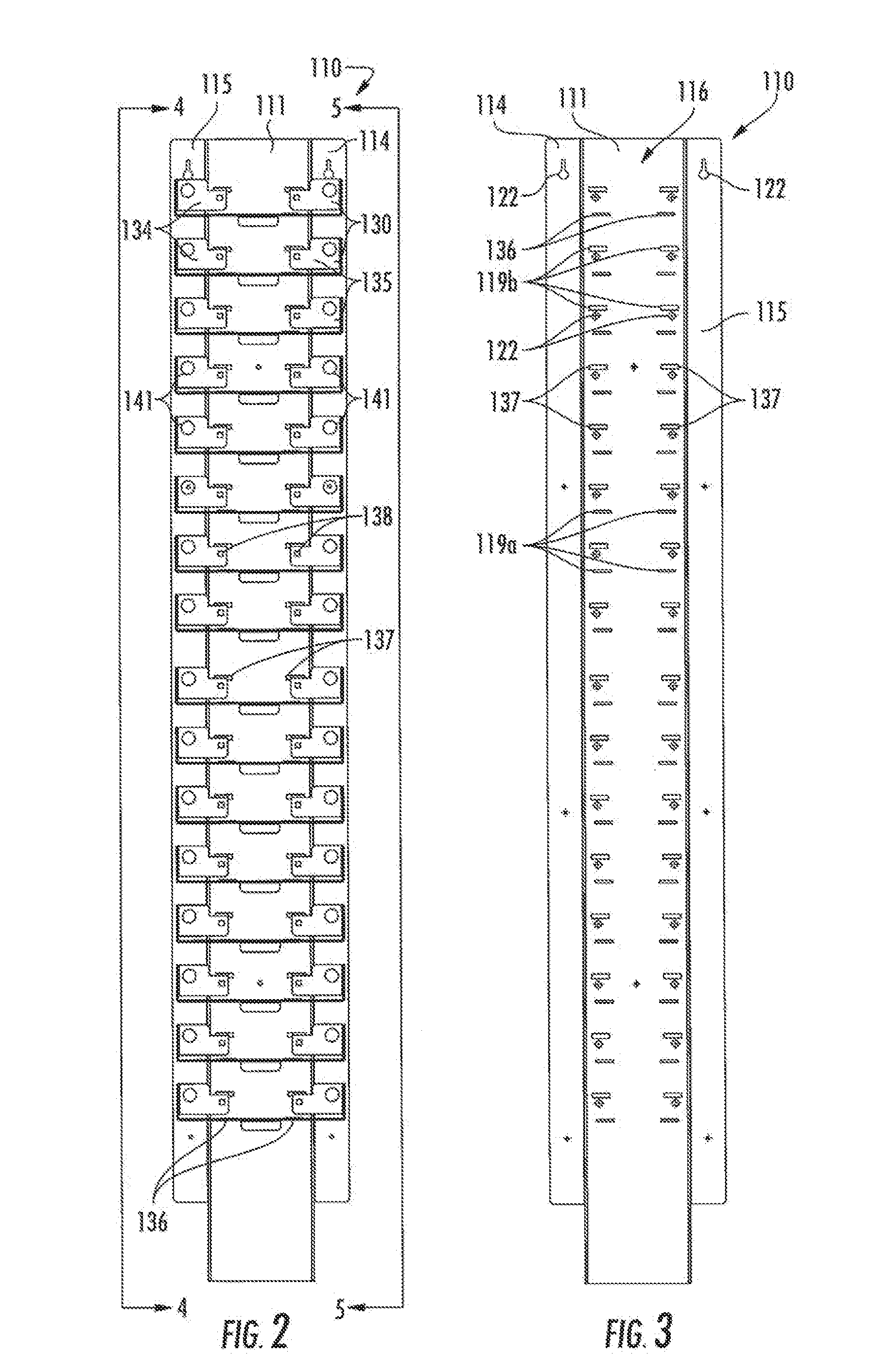
  • Improved storage and charging station system for portable electronic devices

Examples


Embodiment Construction

[0070]The invention illustrated in the Figures and disclosed herein is generally directed to one or more embodiments of a storage and charging station system for portable electronic devices. For ease of discussion and understanding, the following detailed description will at times refer to a “portable electronic device”50, an “electronic device”50, or a “plurality of electronic devices”50. While certain Figures illustrate an electronic device 50 as a laptop computer, it should be appreciated that an electronic device may be any suitable portable electronic device requiring storage and / or battery charging or recharging. For example, an electronic device 50 may include, but is not limited to, a laptop computer, a netbook computer, a notebook computer, a Google Chromebook™ computer, a tablet device (such as an Apple iPad®, Samsung Galaxy®, or Microsoft Surface®, or any similar known or future developed tablet), a mobile smartphone, or any other known or future developed mobile or porta...


PUM


Abstract

A storage and management assembly for a plurality of portable electronic devices is provided. The assembly includes a tower assembly to define a vertical channel along a first side of the tower assembly. A plurality of shelves are removably coupled to a second side of the tower assembly, each of the shelves includes a storage bay defined by a bottom portion provided perpendicular to the first member, and opposing raised edge portions provided about a portion of the perimeter of the bottom portion, the plurality of shelves provided in a stacked vertical arrangement along the tower assembly. A locking assembly having a top wall and sidewalls attached to the shelves, with a pivotable door to prevent removal of electronic devices but permit visual confirmation of shelf contents.

Description

CROSS-REFERENCE TO RELATED APPLICATIONS[0001]This application claims priority to and is a continuation-in-part of U.S. Nonprovisional patent application Ser. No. 15 / 076,260 filed on Mar. 21, 2016, entitled “Improved Storage and Charging Station System for Portable Electronic Devices,” which claims priority to and is a continuation in part of U.S. Nonprovisional patent application Ser. No. 14 / 136,644 filed on Dec. 20, 2013, entitled “Storage and Charging Station System for Portable Electronic Devices,” which claims the benefit of U.S. Provisional Application No. 61 / 745,295 filed on Dec. 21, 2012, and in addition this application claims the benefit of the disclosure of U.S. Provisional Patent Application No. 62 / 135,549 filed on Mar. 19, 2015, entitled “Improved Storage and Charging Station System for Portable Electronic Devices,” and claims the benefit of the disclosure of U.S. Provisional Patent Application No. 62 / 185,375 filed on Jun. 26, 2015, entitled “Improved Mobile Storage and ...

Claims


Application Information

Patent Timeline
Patent Type & Authority Applications(United States)
IPC IPC(8): H02J7/00H05K7/14F16M11/42A45F5/10A47B45/00A47B57/20H05K7/18A47B81/00
CPCH02J7/0027H02J7/0042H05K7/18H05K7/14A47B81/00A45F5/10A45F2200/0516A47B57/20F16M11/42A47B2097/006A47B2097/003A45F2200/0525A47B45/00A45C11/00A45C13/02A45C15/00H02J7/0044H04B1/3888H04M1/04A45C2011/002A45C2011/003G06F1/1632H02J7/0013H02J2310/22
Inventor ROBERTS, NATHAN R.
Owner ROBERTS NATHAN R
Learn More