Gyratory crusher main shaft and assembly
a technology of gyratory crusher and main shaft, which is applied in the direction of grain treatment, etc., can solve the problems of large wall thickness, difficult disassembly, and many problems with conventional protective sleeves
- Summary
- Abstract
- Description
- Claims
- Application Information
AI Technical Summary
Benefits of technology
Problems solved by technology
Method used
Image
Examples
Embodiment Construction
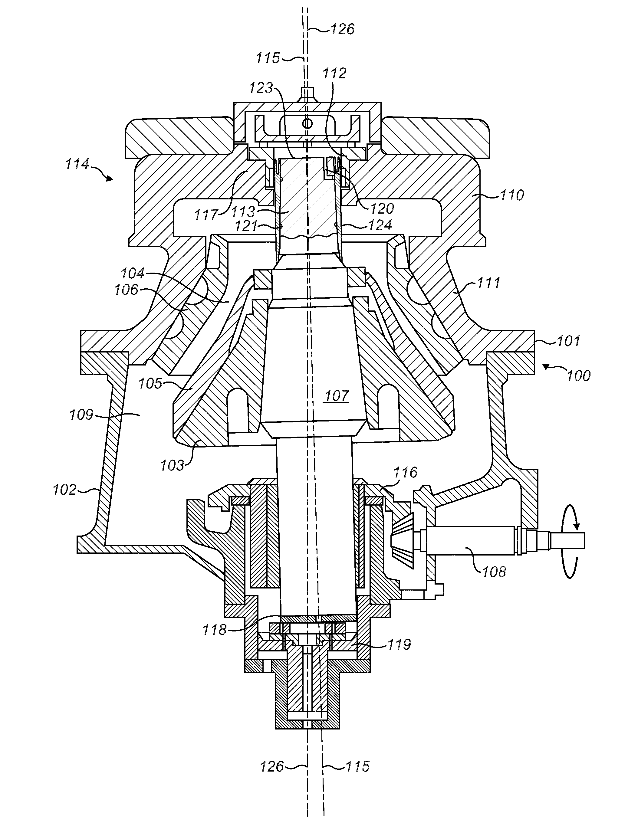
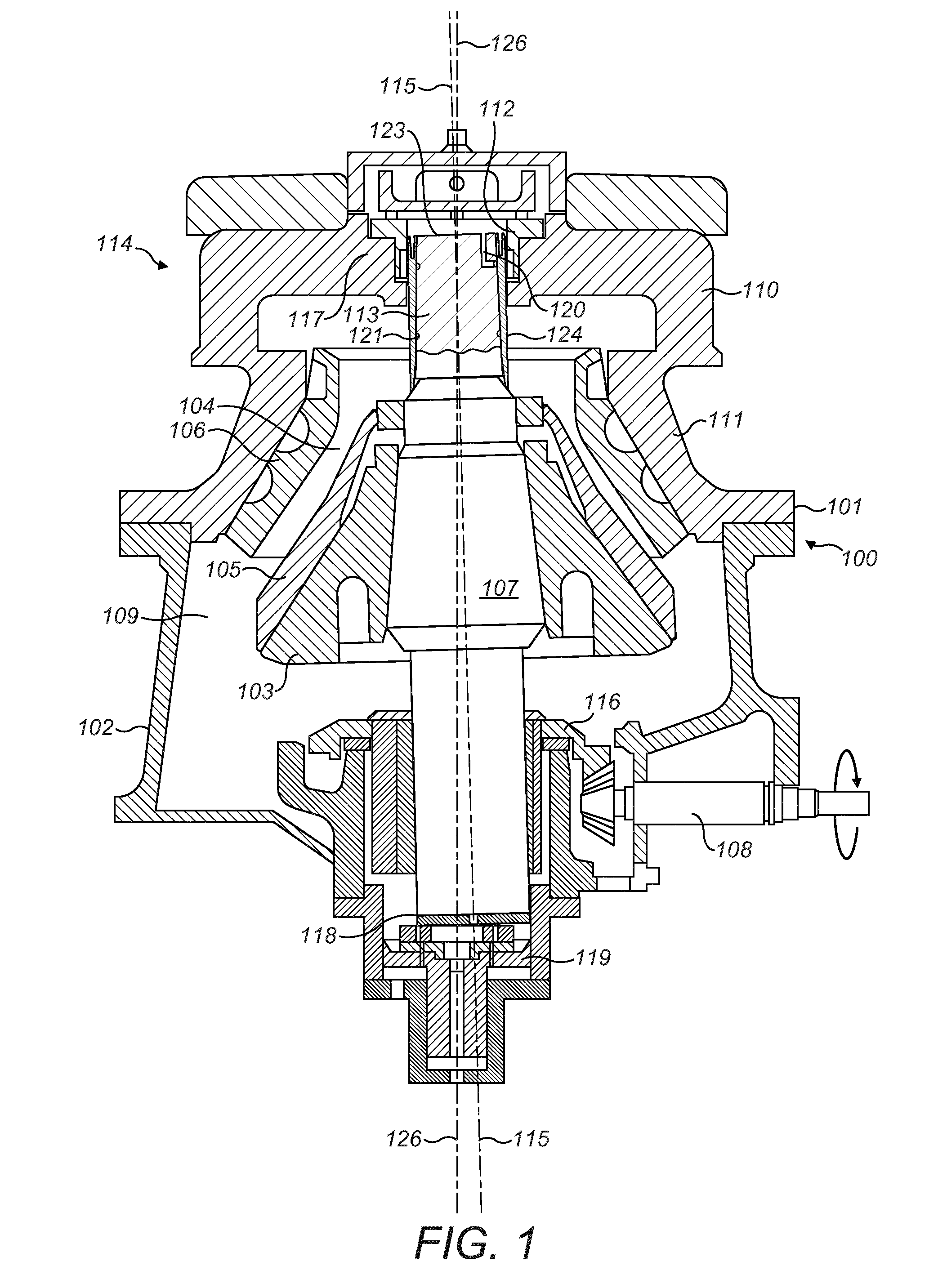
[0025]Referring to FIG. 1, a crusher comprises a frame 100 having an upper frame 101 and a lower frame 102. A crushing head 103 is mounted upon an elongate shaft 107 having a longitudinal axis 115. A first (inner) crushing shell 105 is fixably mounted on crushing head 103 and a second (outer) crushing shell 106 is fixably mounted at upper frame 101. A crushing zone 104 is formed between the opposed crushing shells 105, 106. A discharge zone 109 is positioned immediately below crushing zone 104 and is defined, in part, by lower frame 102.
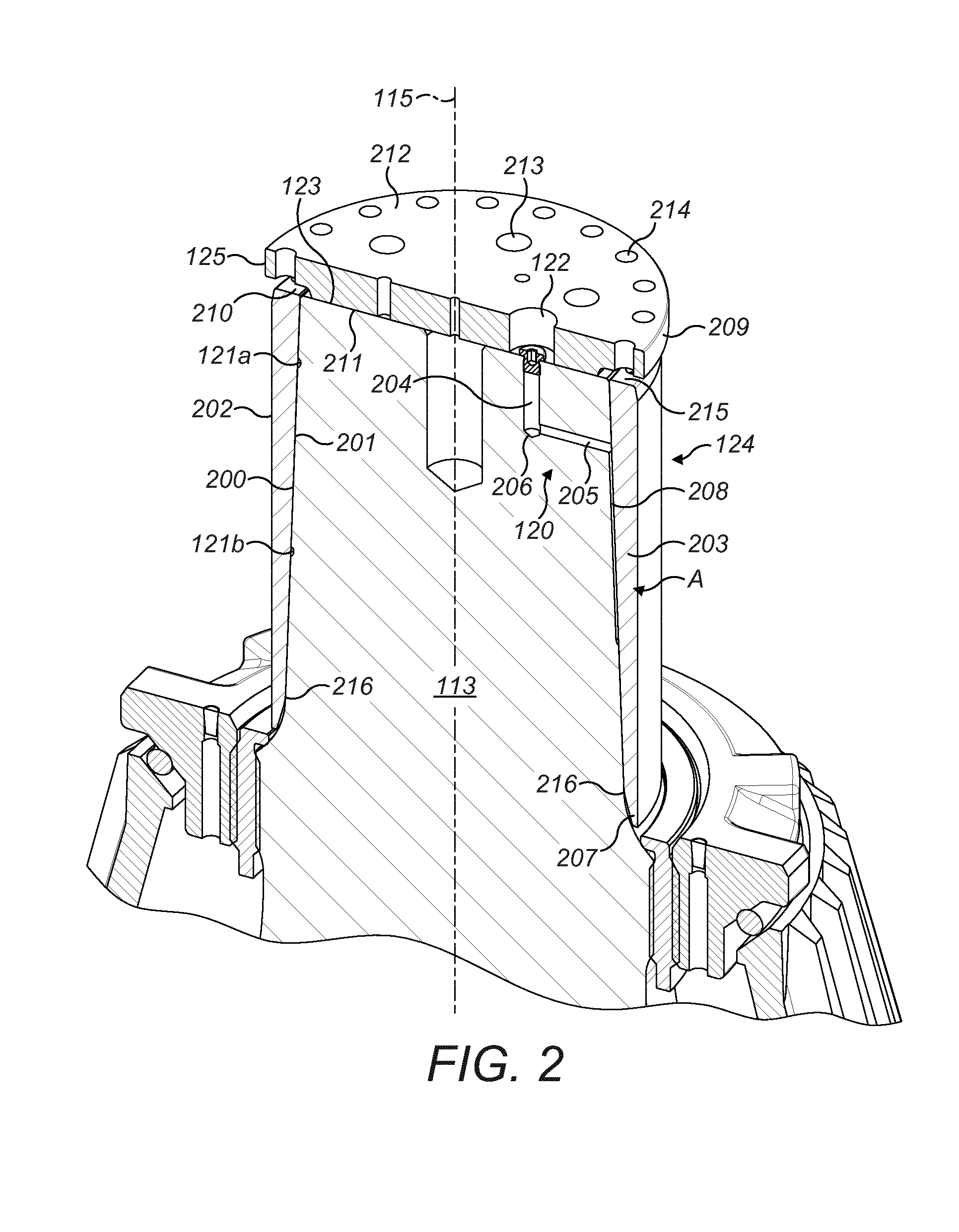
[0026]A drive (not shown) is coupled to main shaft 107 via a drive shaft 108 and suitable gearing 116 so as to rotate shaft 107 eccentrically about a longitudinal axis 126 of the crusher and to cause head 103 to perform a gyratory pendulum movement and crush material introduced into crushing chamber 104. A first (axial upper) end region 113 of shaft 107 is maintained in a rotatable position by a top-end bearing assembly 112 positioned intermediate be...
PUM
 Abstract
Description
Claims
Application Information
 - R&D
- Intellectual Property
- Life Sciences
- Materials
- Tech Scout
- Unparalleled Data Quality
- Higher Quality Content
- 60% Fewer Hallucinations
Browse by: Latest US Patents, China's latest patents, Technical Efficacy Thesaurus, Application Domain, Technology Topic, Popular Technical Reports.
© 2025 PatSnap. All rights reserved.Legal|Privacy policy|Modern Slavery Act Transparency Statement|Sitemap|About US| Contact US: help@patsnap.com


