
Fluid treatment apparatus and process

a technology of treatment apparatus and flue gas, which is applied in the direction of chemistry apparatus and processes, transportation and packaging, mixing, etc., can solve the problems of low dissolved gas level, low gas hold-up, and low shear and reynolds number generated by the mixing action of the agitator, so as to reduce the consumption of cyanide and improve the effect of metal leaching and increasing the opportunities

Active Publication Date: 2016-09-22
SINGH ASHOK ADRIAN
View PDF2 Cites 1 Cited by
  • Summary
  • Abstract
  • Description
  • Claims
  • Application Information

AI Technical Summary

Benefits of technology

This patent describes a process for separating metals such as gold from detail-level analysis of slurried materials. The process involves using a fluid jet to create bubbles and cavitation, which can lead to the oxidation of the metal and improve its leaching and flotation from the slurry. This "technical effect" can help reduce the amount of cyanide consumed in the process and increase the efficiency of metal separation.

Problems solved by technology

A problem occurs, however, in ensuring that the oxygen is sufficiently diffused within the slurry for oxidation to occur so as to recover the maximum amount of gold from the ore.
A disadvantage of this method, however, is that the shear and Reynolds Numbers generated from the mixing action of the agitator are relatively low.
Large bubbles are thus created, which tend to quickly flash off, resulting in low gas hold-up, low dissolved gas levels and low utilization efficiencies.
For example, relative gas hold-up and utilization efficiencies are still relatively low; there is high wear requiring frequent change outs; and the gas to be injected has to be pressurized to above the back-pressure of the system.
Disadvantages, however, are that the system is not under pressure; larger bubbles are created which can flash off; and the gas hold-up and gas utilization efficiencies are relatively low.

Method used


Image

  • Fluid treatment apparatus and process
  • Fluid treatment apparatus and process
  • Fluid treatment apparatus and process

Examples


Embodiment Construction

[0053]In the process of the invention in which a gas is to be dispersed in a fluid, the gas is injected into the fluid such that ultra-fine bubbles are formed, preferably below 1 micrometre in diameter and even more preferably in the picometre diameter range, such that the tiny bubbles behave like solid spheres in the liquid and do not coalesce or flash off. The creation of ultra-fine bubbles increases the gas hold-up in the fluid; increases the mass transfer of gas into fluid; accelerates chemical reactions; and facilitates the flotation of ultra-fine particles.

[0054]Although the invention is described herein in detail for the recovery of gold from ore and for the dissolution of oxygen into a slurry or pulp of milled ore, water and cyanide, it will be apparent to a person skilled in the art that the invention could have many other applications. These include the pre-oxidation of mineral pulps; accelerated leaching of various metal values in the minerals industry, e.g. gold, platinu...


PUM

PropertyMeasurementUnit
cone angleaaaaaaaaaa

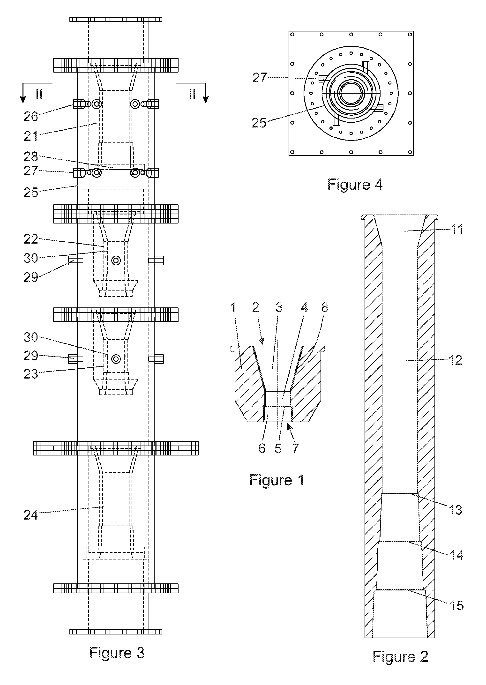
Abstract

Liquid treatment apparatus comprises at least two chambers being first and second chambers through which a fluid can flow. The two chambers are separated by at least one choke nozzle which has an entrance in the first chamber and an exit in the second chamber. The choke nozzle (1) comprises a converging section at its entrance (3), a throat section (4), a backward-facing step (5) immediately after the throat section (4), and an exit section at its exit (6) wherein the exit section (6) diverges from the step (5). Similarly constructed mixing nozzles (1) may be included in the apparatus. The apparatus is especially useful in processes requiring a gas to be entrained in a fluid so that the gas is in the form of very small bubbles that do not tend to coalesce and flash off such as in the dissolution of gold and other precious metals from ore in the removal of arsenic from an ore.

Description

FIELD OF THE INVENTION[0001]The invention relates to fluid treatment apparatus for treating a fluid medium including a slurry or pulp and, more particularly, to an apparatus and process for enhancing chemical or physical reactions occurring in processes by utilizing choked flow and may provide associated hydraulic cavitation.[0002]Application of the invention includes not only reactions and processes that take place in a single or multiple fluid phase but also those in which one or more fluids and a gas are contacted such as in a process in which a liquid and at least a component of the gas partake in a physical or chemical reaction. Application of the invention thus extends to chemical extraction processes such as the extraction of precious metals including gold in which a slurry or pulp and an oxidizing gas are mixed and subjected to choked flow; the destruction of cyanide to lower levels of residual cyanide in waste process solutions pulps and slurries; and the removal of arsenic...

Claims


Application Information

Patent Timeline
Patent Type & Authority Applications(United States)
IPC IPC(8): B01F5/04B01F5/00B01J19/26C22B11/08C22B3/12C22B3/22B01F3/04C22B3/00
CPCB01F5/0416B01F3/04503B01F5/0065B01F5/0423B01F5/0421B01F2005/0441C22B11/08C22B3/12C22B3/22B01J19/26C22B11/04C22B3/02B01F2215/0422B03D1/242Y02P10/20B01F23/2323B01F25/103B01F25/3122B01F25/31233B01F25/31232B01F25/31242B01F25/31423B01F25/3141B01F25/432B01F23/20B01F25/72C22B7/008B01F25/31243
Inventor SINGH, ASHOK ADRIAN
Owner SINGH ASHOK ADRIAN
Learn More