
Handpiece assembly for an apparatus used in cosmetic treatment

a technology for cosmetic treatment and handpieces, applied in the field of cosmetic treatment devices and systems, can solve the problems of complex replacement parts production costs, device and system constraints, laborious and time-consuming procedures, etc., and achieve the effects of reducing production costs, reducing a number of “spare parts”, and high performance efficiency

Inactive Publication Date: 2016-09-22
CRYOTECH NORDIC OU
View PDF6 Cites 44 Cited by
  • Summary
  • Abstract
  • Description
  • Claims
  • Application Information

AI Technical Summary

Benefits of technology

The present invention provides a handpiece assembly for cosmetic treatment that can change or replace the treatment head without replacing the entire structure, reducing production costs. It also allows for real-time monitoring of subcutaneous tissue temperature to prevent skin and subcutaneous tissue damage. The cooling units are compact, light-weight, and efficient, utilizing flat heat pipe technology instead of common water circulation channels' containing heat exchangers. The handpiece assembly is designed to provide high performance and reliability in thermal management systems.

Problems solved by technology

Above mentioned devices and systems are constrained with common technical problems.
Such a procedure is laborious and time-consuming.
Moreover, production costs for complex replacement parts, comprising e.g. a fluidic conduit fixedly associated with a treatment head, are high, which affects also maintenance expenses and market pricing for an actual treatment.
Another constraint concerns incapability of known cryolipolysis devices to monitor tissue temperature within the treated area.
Other drawbacks of some existing devices for cryolipolysis include insufficient efficiency of the cooling units and / or heat exchangers utilized therewithin, originated from low heat transfer rates with regards to small footprint area, which results in excessive energy consumption by these devices.

Method used


Image

  • Handpiece assembly for an apparatus used in cosmetic treatment
  • Handpiece assembly for an apparatus used in cosmetic treatment
  • Handpiece assembly for an apparatus used in cosmetic treatment

Examples


Embodiment Construction

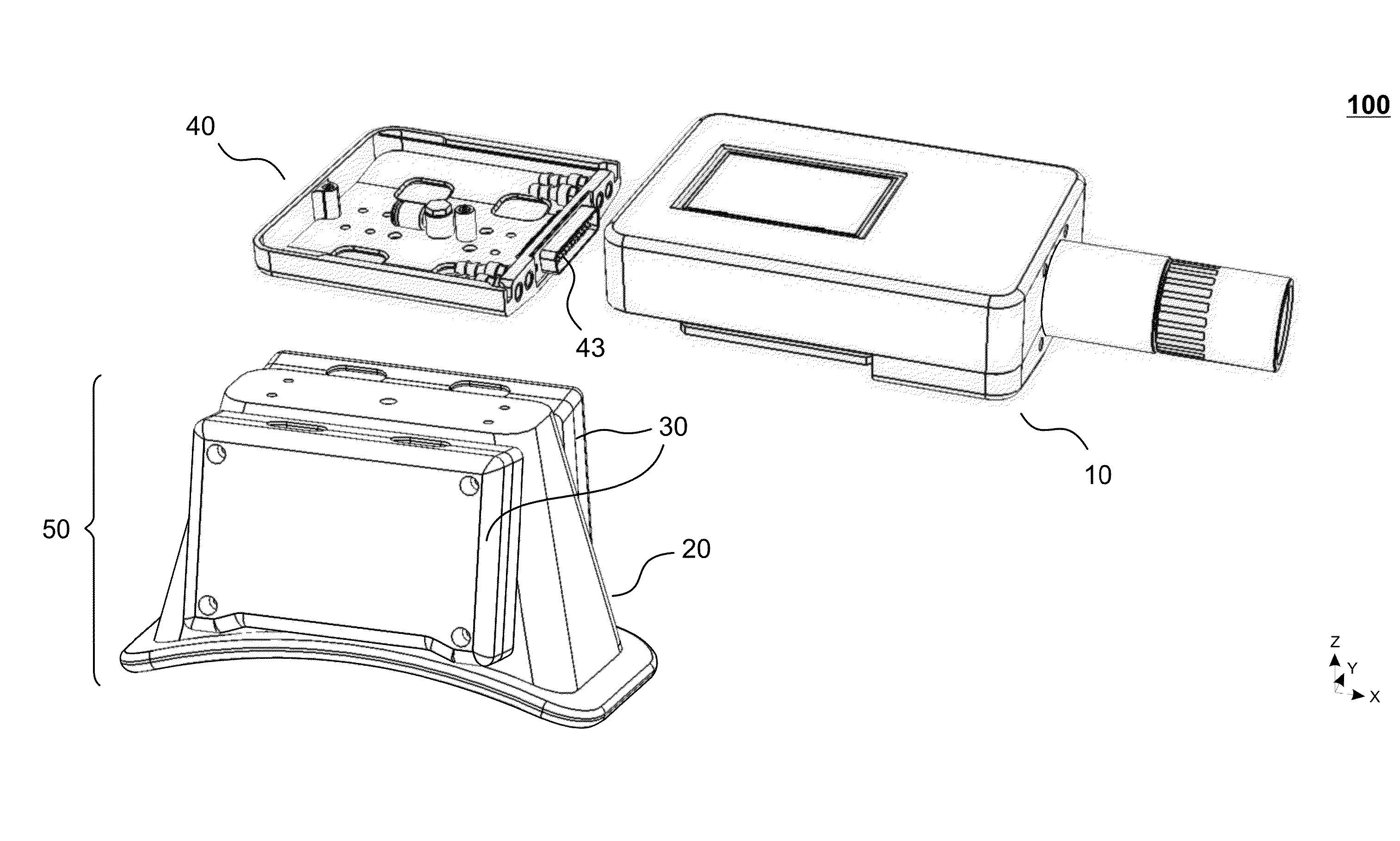
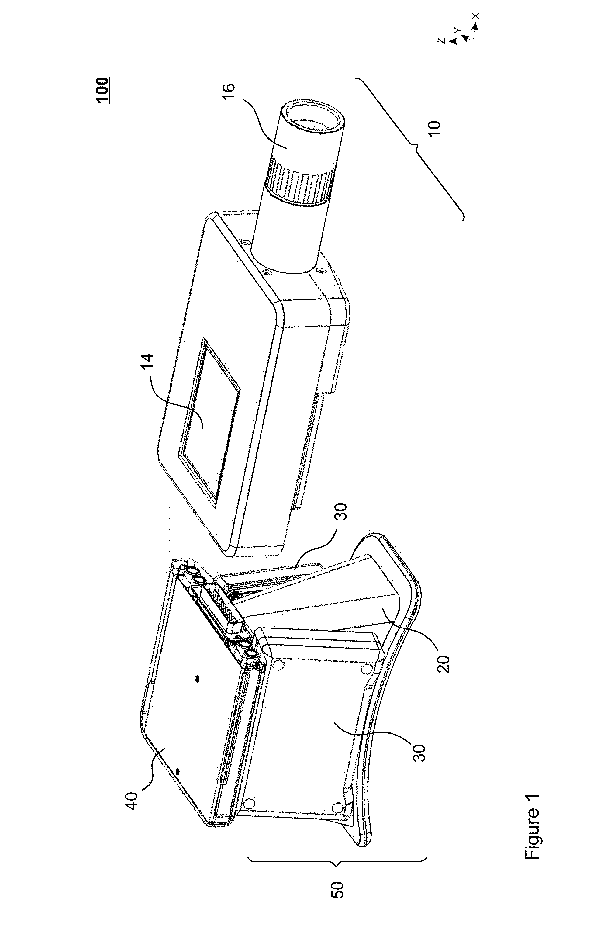
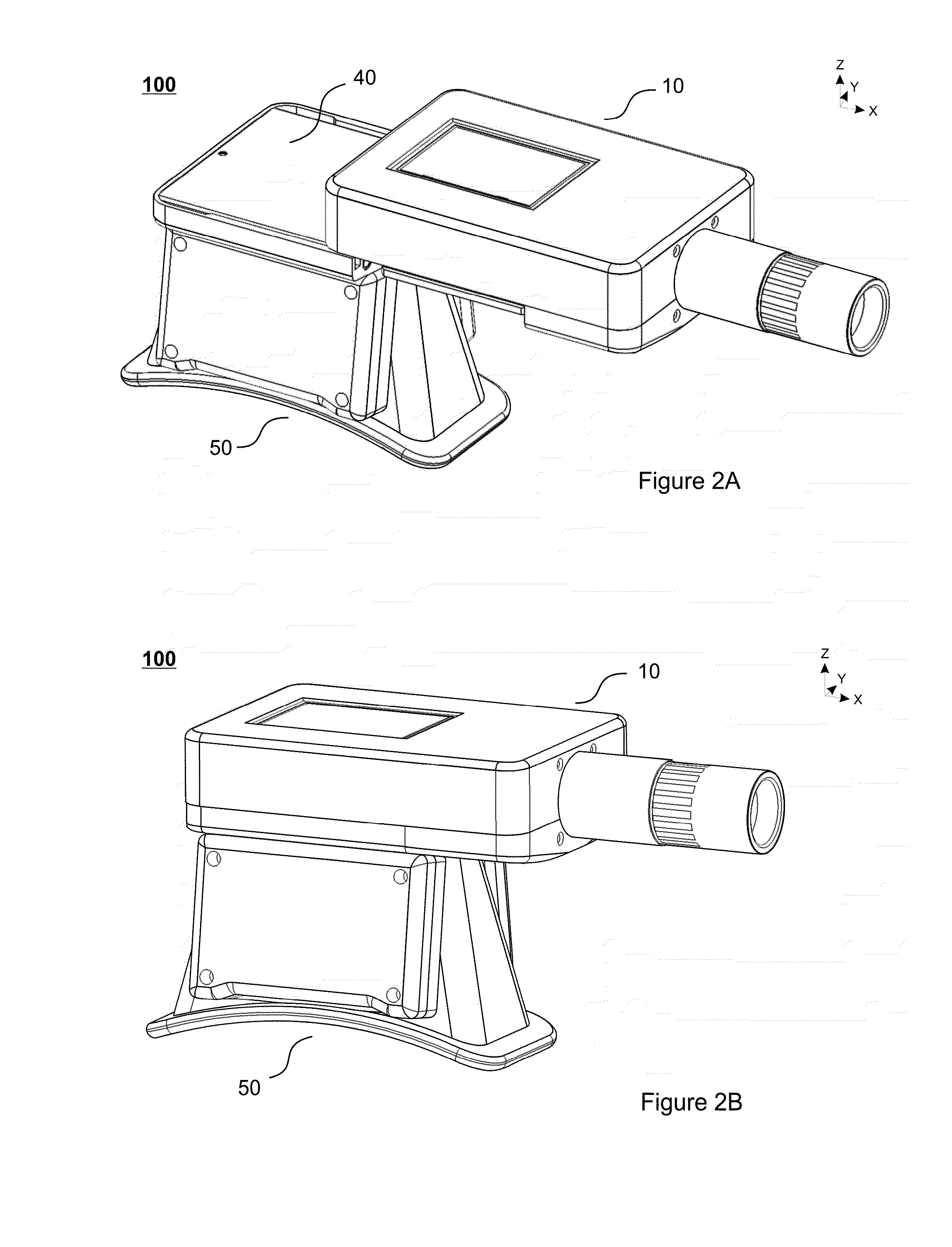
[0038]Detailed embodiments of the present invention are disclosed herein with the reference to accompanying drawings. The same reference characters are used throughout the drawings to refer to same members. Following citations are used for the members:[0039]100—a handpiece assembly;[0040]10—a handle;[0041]11a, b, c—casing components;[0042]12—a protection plate (handle);[0043]13—a connector;[0044]14—a control terminal / user interface;[0045]15—fittings (handle);[0046]16—a fluidic line connector / adjusting control device;[0047]17—an aperture (handle);[0048]20—a vacuum cup applicator;[0049]21—a frame (vacuum cup applicator);[0050]22—an edge (vacuum cup applicator);[0051]23—a side aperture (vacuum cup applicator);[0052]30—a cooling unit;[0053]31—an outer cover;[0054]32—a heat transfer element;[0055]33—a thermoelectric cooler;[0056]34—an inner cover;[0057]35—a first cold plate;[0058]36—a second cold plate;[0059]40—an adapter for the treatment head;[0060]41—a vacuum cup connecting part;[0061...


PUM


Abstract

A handpiece assembly 100 for an apparatus used in non-invasive cosmetic treatment, in particular, in an apparatus for non-invasive fat reduction by cold-induced lipolysis of fat cell, known as cryolipolysis, is provided. The handpiece assembly 100 includes a handle 10, provided with a control terminal 14 equipped with a user interface, the handle 10 being connectable to the treatment unit of the apparatus for cosmetic treatment by a number of fluidic and / or communication lines; a treatment head 50 configured as a cup-shaped body applicator 20 disposed between at least two cooling units 30, and an adapter 40 configured to connect the handle 10 and the treatment head 50, wherein the connection between the handle 10 and the treatment head 50 mediated by the adapter 40 is releasable.

Description

FIELD OF THE INVENTION[0001]The present invention generally relates to cosmetic treatment devices and systems for non-invasive reduction of fat deposits by controlled cooling of adipose tissue; more particularly the invention concerns an improved body applicator device for aforesaid equipment.BACKGROUND THE INVENTION[0002]In recent years a number of newly designed technologies for non-invasive body contouring and reshaping have become available to the consumer. These include reducing body fat deposits by means of high-intensity focused ultrasound, radiofrequency, low-level laser, acoustic waves and controlled cooling of adipose tissue to sub-zero temperatures (Celsius). The latter technique, also known as cryolipolysis, has proved to be one of the safest and most effective procedures for non-invasive body fat removal. Technique of cryolipolysis exploits the premise that adipocytes (fat cells) are more susceptible to low temperatures than other skin cells.[0003]Precise application of...

Claims


Application Information

Patent Timeline
Patent Type & Authority Applications(United States)
IPC IPC(8): A61F7/00A61F7/10
CPCA61F7/007A61F7/10A61F2007/0095A61F2007/0075A61F2007/0086A61F2007/0056A61B18/02A61B2017/0046A61B2018/00172A61B2018/00178A61B2018/00291A61B2018/00452A61B2018/00916A61B2018/0237A61B2018/0243A61B2018/025A61F2007/0052A61F2007/0087A61B2018/00047A61B2018/00791A61F2007/0093A61F2007/0096A61B2017/00199
Inventor MARTINS, JEAN-PATRICKSIMONEN, ARIHIRVONEN, VESAEKLUND, JAN
Owner CRYOTECH NORDIC OU
Learn More