
Top submerged injection lance for enhanced submerged combustion

a technology of submerged injection and injection lance, which is applied in the direction of furnaces, charge manipulation, manufacturing converters, etc., can solve the problems of difficult maintenance of required solid slag coating, difficulty in maintaining bath temperature, so as to improve the combustion of the mixture, improve the effect of maintenance and strong combustion

Active Publication Date: 2016-09-15
METSO OUTOTEC (FINLAND) OY
View PDF2 Cites 3 Cited by
  • Summary
  • Abstract
  • Description
  • Claims
  • Application Information

AI Technical Summary

Benefits of technology

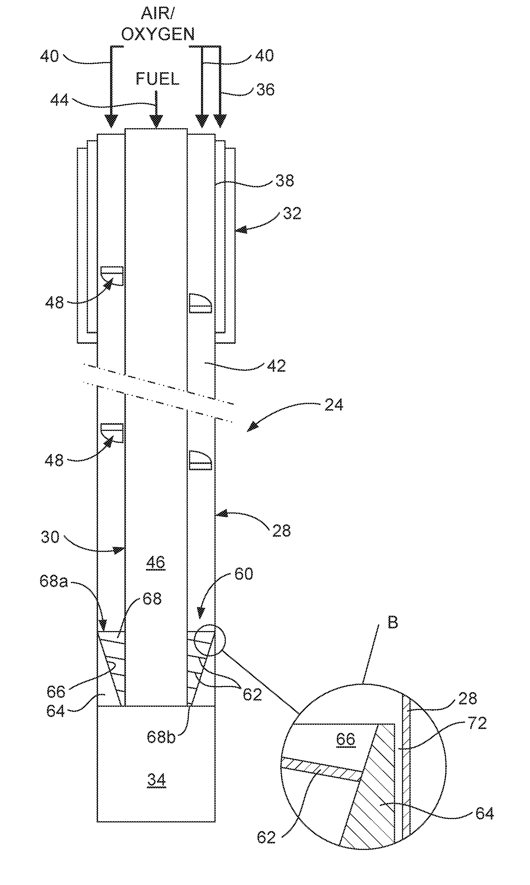
The present invention provides a lance for top submerged injection in a pyro-metallurgical operation that improves mixing of oxygen-containing gas with fuel, enhances combustion of the mixture, and increases the solidified slag coating to maintain it at higher operating temperatures. The lance has a unique design with a concentric annular passage for oxygen-containing gas and a gas flow-modifying device that improves mixing by imparting a flow component away from the inner surface of the outer pipe. This results in a stronger combustion flame that is concentrated away from the inner surface of the outer pipe, reducing the risk of damage to the pipe and increasing the operating efficiency of the lance.

Problems solved by technology

This procedure has been used widely in numerous different pyro-metallurgical processes, although difficulties are encountered in some operations.
For example, mixing of the oxygen-containing gas and the fuel may not be sufficient to achieve efficient combustion of the fuel, resulting in difficulty in maintaining the bath temperature by the submerged combustion and dispersal of fuel within the bath in which the fuel acts, contrary to intentions, as a reducing agent.
Also, particularly at bath temperatures close to the upper end of the temperature range for use in TSL technology, the required solid slag coating can be difficult to maintain and, where that coating is lost, rapid erosion of the outermost pipe occurs.
At such higher temperatures, the cooling effect provided by the oxygen-containing gas can be inadequate for cooling the outermost pipe, while the combustion flame can pass too close to the inner surface of the outermost pipe and further exacerbate the difficulty in adequately cooling the outermost pipe.

Method used


Image

  • Top submerged injection lance for enhanced submerged combustion
  • Top submerged injection lance for enhanced submerged combustion
  • Top submerged injection lance for enhanced submerged combustion

Examples


Embodiment Construction

[0049]Before directly addressing the drawings, it is pertinent to note that a TSL lance according to the invention, as with TSL lances in general, necessarily is of large dimensions. At a location remote from the outlet end, such as adjacent to an upper or inlet end, the lance has a structure by which it can be suspended so as to hang down vertically within a TSL reactor. The lance may have a length as short as about 7.5 metres, such as for a small special purpose TSL reactor. The lance may be up to about 25 metres in length, or even greater, for a special purpose large TSL reactor. More usually, the lance ranges from about 10 to 20 metres in length. These dimensions relate to the overall length of the lance and the outermost pipe through to the outlet end. The next adjacent pipe, and the innermost and any other pipe for a lance with at least three substantially concentric pipes, may extend to the outlet end and therefore be of substantially the same overall length as the outermost ...


PUM

PropertyMeasurementUnit
Flow rateaaaaaaaaaa
Lengthaaaaaaaaaa
Widthaaaaaaaaaa

Abstract

A lance for top submerged lancing injection in a pyro-metallurgical operation, wherein the lance has at least two substantially concentric pipes, with an annular passage for oxygen-containing gas defined between an outermost one of the pipes and a next adjacent pipe and a further passage for fuel defined within an innermost one of the pipes; the outermost pipe has a lower part of its length, from a submergible lower outlet end of the lance, by which the outermost pipe extends beyond an outlet end of the or each other pipe to define between the outlet end of the outermost pipe and the outlet end of the or each other pipe a chamber with which the passage for oxygen-containing gas communicates; and the lance further includes a defined gas flow-modifying device that is disposed in a lower end section of the passage for oxygen-containing gas.

Description

TECHNICAL FIELD[0001]This invention relates to top submerged injecting lances for use in molten bath pyro-metallurgical operations.BACKGROUND TO THE INVENTION[0002]The following discussion of the background to the invention is intended to facilitate an understanding of the invention. However, it should be appreciated that the discussion is not an acknowledgement or admission that any of the material referred to was published, known or part of the common general knowledge as at the priority date of the application.[0003]Molten bath smelting operations, or other pyro-metallurgical operations that require interaction between the bath and a source of oxygen-containing gas, utilize several different arrangements for the supply of the gas. In general, these operations involve direct injection into molten matte / metal. This may be by bottom blowing tuyeres as in a Bessemer type of furnace or side blowing tuyeres as in a Peirce-Smith type of converter. Alternatively, the injection of gas may...

Claims


Application Information

Patent Timeline
IPC IPC(8): F27B3/22C21C5/46
CPCF27B3/225F27D2003/169F27D2003/162C21C5/4613F27B3/22C21C5/4606
Inventor REUTER, MARKUSMATUSEWICZ, ROBERT WALTERXIA, JILIANGJACOBSON, NEIL
Owner METSO OUTOTEC (FINLAND) OY
Learn More