Lamp
a technology for lamps and adjusting members, applied in the field of lamps, can solve the problems of disordered visual effect in space, damage to externally exposed adjusting members, etc., and achieve the effect of keeping the appearance of the exterior of the lamp unchanged
- Summary
- Abstract
- Description
- Claims
- Application Information
AI Technical Summary
Benefits of technology
Problems solved by technology
Method used
Image
Examples
first embodiment
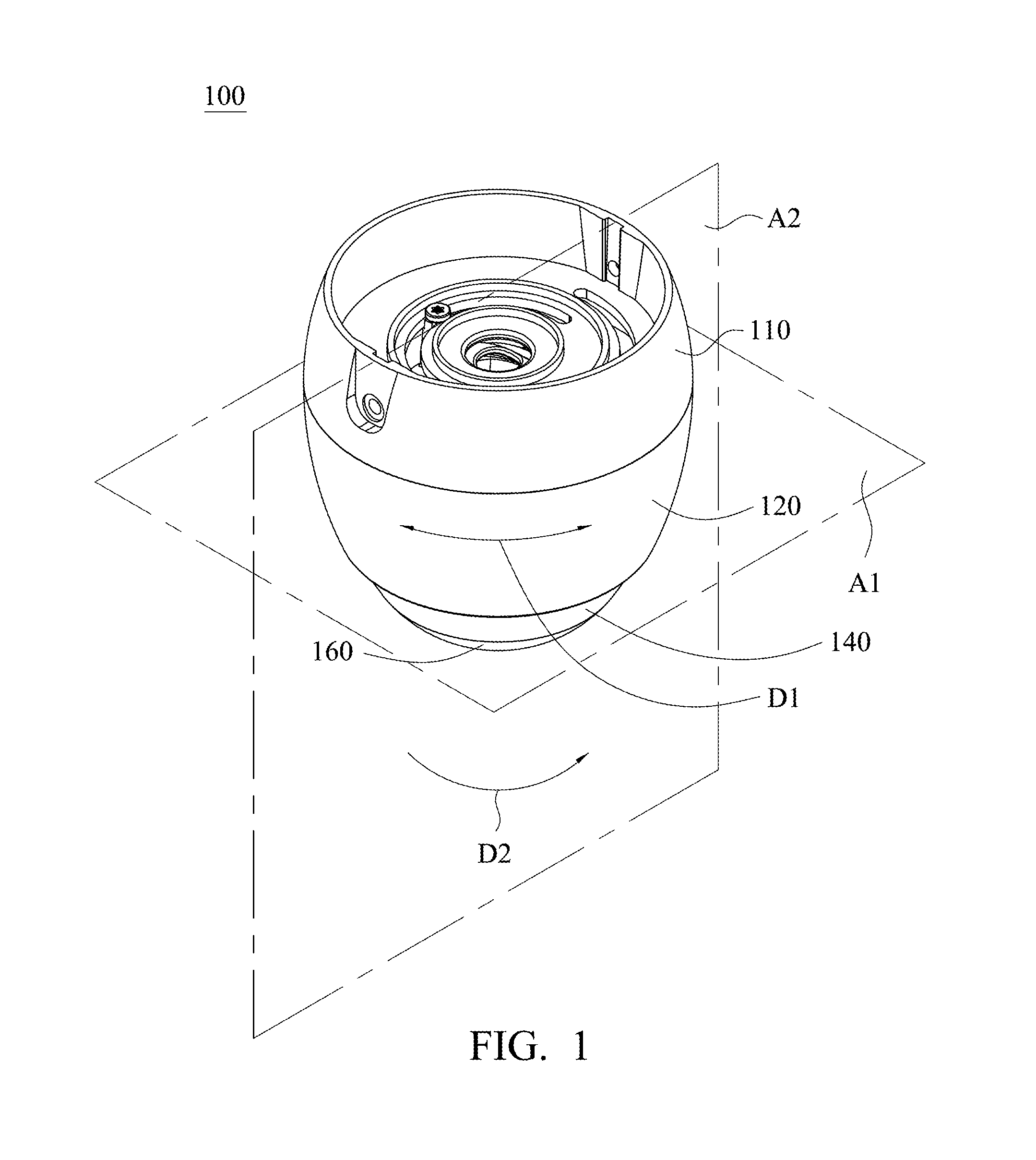
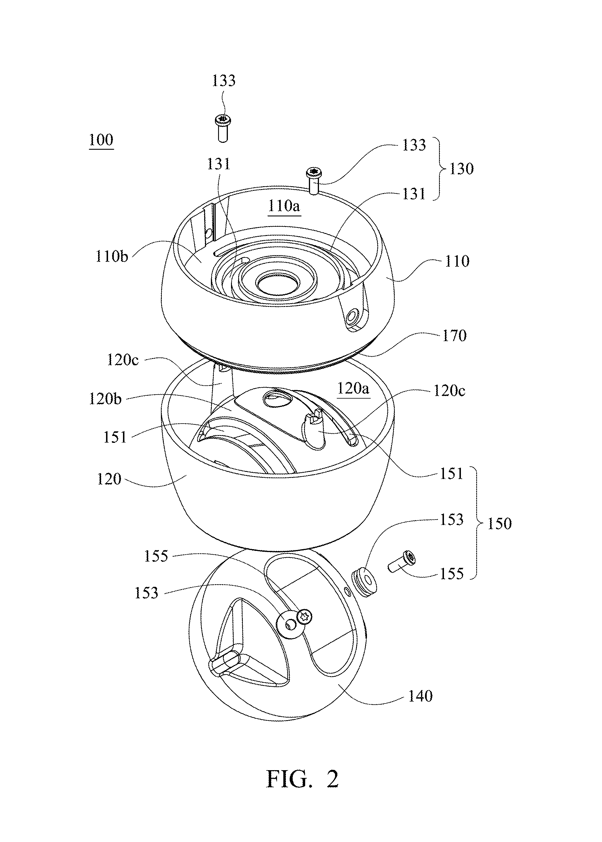
[0060]Simultaneously referring to FIG. 1 and FIG. 2, FIG. 1 and FIG. 2 are a schematic diagram and a schematic exploded view showing a lamp 100 in accordance with the present invention. The lamp 100 mainly includes a rotary adjustment mechanism 130, an inclination adjustment mechanism 150 and a light source 160. As shown in FIG. 1, the light source 160 is rotatable along a first direction D1 in a first plane A1 by the rotary adjustment mechanism 130 and / or rotatable relative along a second direction D2 in a second plane A2 by the inclination adjustment mechanism 150. In the present embodiment, the second plane A2 is different from the first plane A1. As shown in FIG. 1 and FIG. 2, the lamp 100 further includes a lamp base 110, a case body 120 and a spherical shell 140. The rotary adjustment mechanism 130 is disposed in an inner space 110a of the lamp base 110 and / or an inner space 120a of the case body 120, and the rotary adjustment mechanism 130 can be used to connect the lamp base...
second embodiment
[0070]In the present invention, the lamp 100 may have different designs. Referring to FIG. 10 to FIG. 12, FIG. 10 to FIG. 12 are a schematic diagram, a schematic exploded view showing and a partial cross-sectional view showing a lamp 300 in accordance with the present invention. The lamp 300 mainly includes a rotary adjustment mechanism 330, an inclination adjustment mechanism 350 and a light source 360. As shown in FIG. 10, the light source 360 is rotatable along a first direction D3 in a first plane A3 by the rotary adjustment mechanism 330 and / or rotatable relative along a second direction D4 in a second plane A4 by the inclination adjustment mechanism 350. In the present embodiment, the second plane A4 is different from the first plane A3. As shown in FIG. 10 to FIG. 12, the lamp 300 further includes a lamp base 310, a case body 320 and a spherical shell 340. The rotary adjustment mechanism 330 is mainly disposed in an inner space 310a of the lamp base 310 and / or an inner space ...
third embodiment
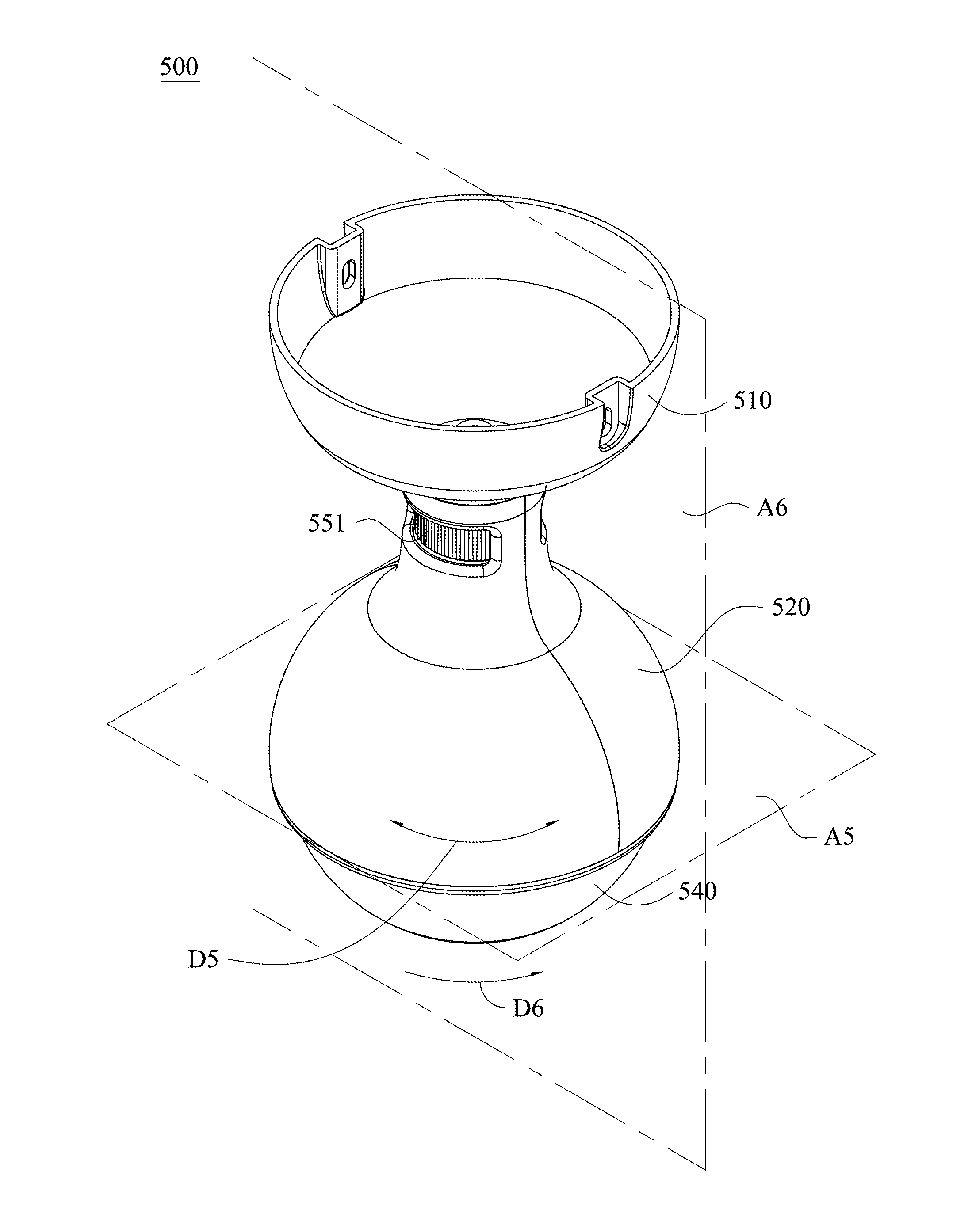
[0078]In the present invention, the lamp 300 may have different designs. Referring to FIG. 16 to FIG. 18, FIG. 16 to FIG. 18 are a schematic diagram, a schematic exploded view and a partial cross-sectional view showing a lamp 500 in accordance with the present invention. The lamp 500 mainly includes a rotary adjustment mechanism 530, an inclination adjustment mechanism 550 and a light source 560. As shown in FIG. 1, the light source 560 is rotatable along a first direction D5 in a first plane A5 by the rotary adjustment mechanism 530 and / or rotatable relative along a second direction D6 in a second plane A6 by the inclination adjustment mechanism 550. In the present embodiment, the second plane A6 is different from the first plane A5. As shown in FIG. 16 to FIG. 18, the lamp 500 further includes a lamp base 510, a case body 520 and a spherical shell 540. The rotary adjustment mechanism 530 is disposed in an inner space 510a of the lamp base 510 and / or an inner space 520a of the case...
PUM
 Abstract
Description
Claims
Application Information
 - R&D
- Intellectual Property
- Life Sciences
- Materials
- Tech Scout
- Unparalleled Data Quality
- Higher Quality Content
- 60% Fewer Hallucinations
Browse by: Latest US Patents, China's latest patents, Technical Efficacy Thesaurus, Application Domain, Technology Topic, Popular Technical Reports.
© 2025 PatSnap. All rights reserved.Legal|Privacy policy|Modern Slavery Act Transparency Statement|Sitemap|About US| Contact US: help@patsnap.com


