Highly-Secure Wireless Communication System
a wireless communication system and high-security technology, applied in wireless communication, diversity/multi-antenna systems, polarisation/directional diversity, etc., can solve the problems of easy intercept or alter data, difficult control of equipment using data, and severe blow to civilian lives
- Summary
- Abstract
- Description
- Claims
- Application Information
AI Technical Summary
Benefits of technology
Problems solved by technology
Method used
Image

Examples
example 1
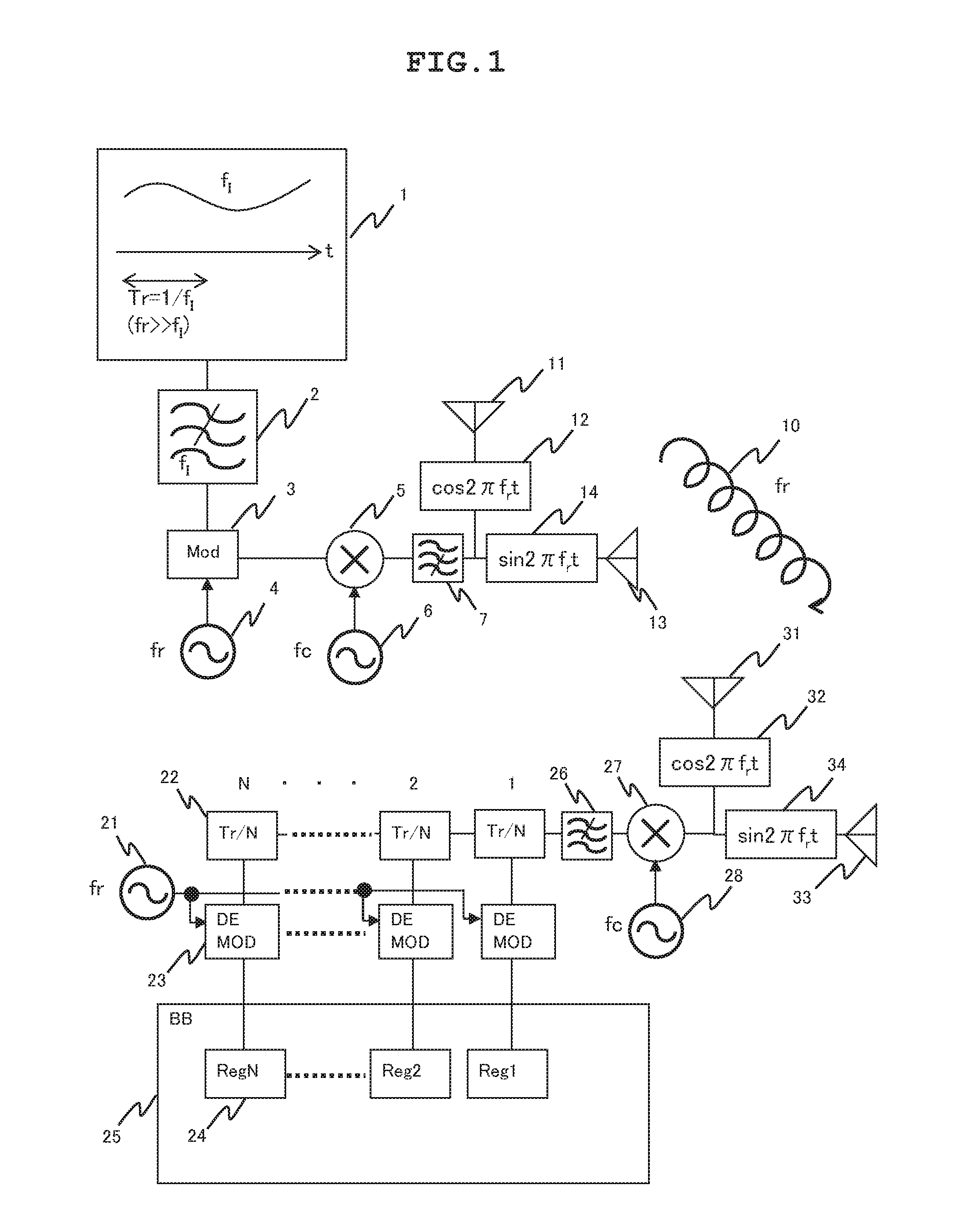
[0032]FIG. 1 is a diagram showing an example of configurations of a transmitter and receiver constituting a wireless system of the present example. In the transmitter, a band limiting filter 2 determines the upper limit of frequencies contained in a signal that falls within a frequency band (fl) and is produced by an information signal production circuit 1. A modulation circuit 3 convolutes a circularly polarized wave frequency carrier (fr) 4 to the signal. A harmonic mixer 5 convolutes a transmission carrier frequency carrier (fc) 6 to the signal. A spurious removing filter 7 removes an unnecessary harmonic component from the signal. A cosine weighting circuit 12 controls the amplitude of the signal. The signal is then radiated from a transmitting vertical antenna 11. At the same time, the signal whose amplitude is controlled by a sine weighting circuit 14 is radiated to the space from a transmitting horizontal antenna 13. Thus, a circularly polarized electromagnetic wave 10 that p...
example 2
[0037]FIG. 3 is a diagram showing another example of configurations of a transmitter and receiver constituting the wireless communication system of the present example. A difference from the example shown in FIG. 1 is that the receiver further includes a dummy signal generation circuit 15. The dummy signal generation circuit 15 generates a dummy signal that has nothing to do with an information signal, which should be sent from the transmitter, during a period equivalent to a value (Tr / N) obtained by dividing the cycle (Tr) of a circularly polarized wave by an integer. In the present example, an adaptive phase shifter (Txi) 16 and adder 17 are newly included. The adaptive phase shifter (TXi) 16 is adjusted so that the dummy signal generated by the dummy signal generation circuit 15 can be transmitted at an angle of polarization equivalent to a period during which an externally intentional alteration activity detected by the baseband circuit 25 takes place. The angle of polarization ...
example 3
[0039]FIG. 4 is a diagram showing another example of configurations of a transmitter and receiver constituting a wireless system of the present example. A difference from the transmitter in the example shown in FIG. 1 is that a block code production circuit 19 that produces a different block code during each of division periods into which the cycle of a rotational frequency is divided by an integer is substituted for the circularly polarized wave frequency carrier (fr) 4, and a multiplier 18 is substituted for the modulation circuit 3 in order to convolute the block codes, which are produced by the block code production circuit 19, to an information signal. A difference from the receiver in the example shown in FIG. 1 is that an integral number of signal components is stored in the respective registers 24 as they are via the retarder 22, which cascades a frequency component of the circularly polarized wave and a frequency component of the information signal, while being provided wit...
PUM
 Abstract
Description
Claims
Application Information
 - R&D
- Intellectual Property
- Life Sciences
- Materials
- Tech Scout
- Unparalleled Data Quality
- Higher Quality Content
- 60% Fewer Hallucinations
Browse by: Latest US Patents, China's latest patents, Technical Efficacy Thesaurus, Application Domain, Technology Topic, Popular Technical Reports.
© 2025 PatSnap. All rights reserved.Legal|Privacy policy|Modern Slavery Act Transparency Statement|Sitemap|About US| Contact US: help@patsnap.com