Balloon catheter

Inactive Publication Date: 2016-09-01
AHN YONG CHUL
View PDF1 Cites 9 Cited by
  • Summary
  • Abstract
  • Description
  • Claims
  • Application Information

AI Technical Summary

Benefits of technology

The present invention introduces a balloon catheter that can improve the reliability and convenience of surgical treatment. The balloon catheter is low-cost and easy to make. Overall, it provides a better solution for reliably and conveniently performing surgical treatment.

Problems solved by technology

Thus, when the pressure of fluid applied to the balloon is inaccurately controlled such that an excessive amount of pressure is applied to the balloon, the balloon may be inflated beyond a required level, thereby being deformed to an abnormal shape different from a required shape.
An abnormally-inflated shape balloon may lead to treatment difficulty and may significantly lower the accuracy of the surgical treatment.
However, this process is very complicated and is disadvantageous in terms of the speed of the surgical treatment, the improvement of which is required.
Since the inflating lumen and the guide wire lumen are separately provided on the catheter tube in this manner, it is difficult to fabricate the balloon catheter.
In addition, the balloon catheter has a complicated structure, and the outer diameter of the catheter tube has to be increased.

Method used


Image

  • Balloon catheter
  • Balloon catheter
  • Balloon catheter

Examples


first embodiment

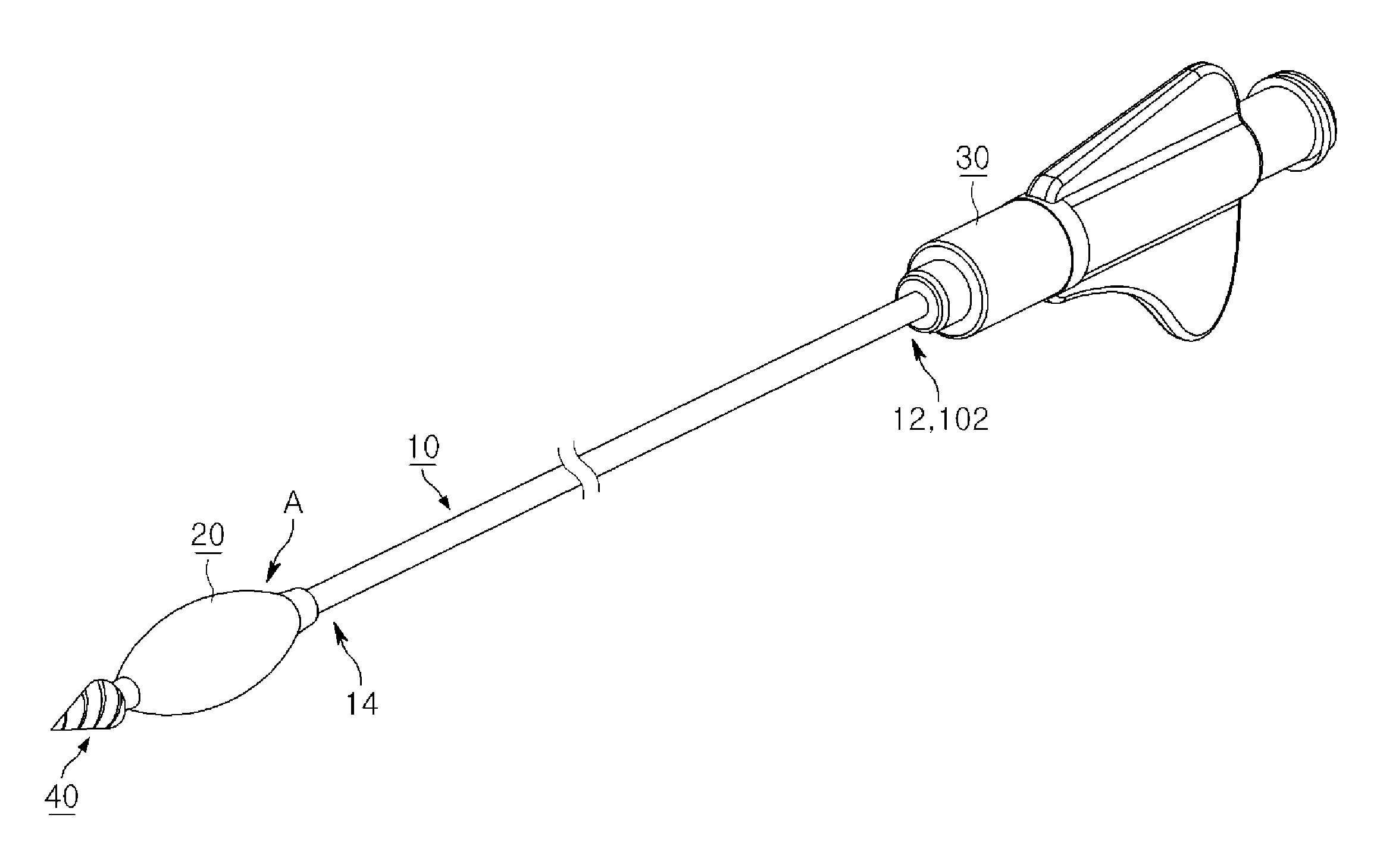
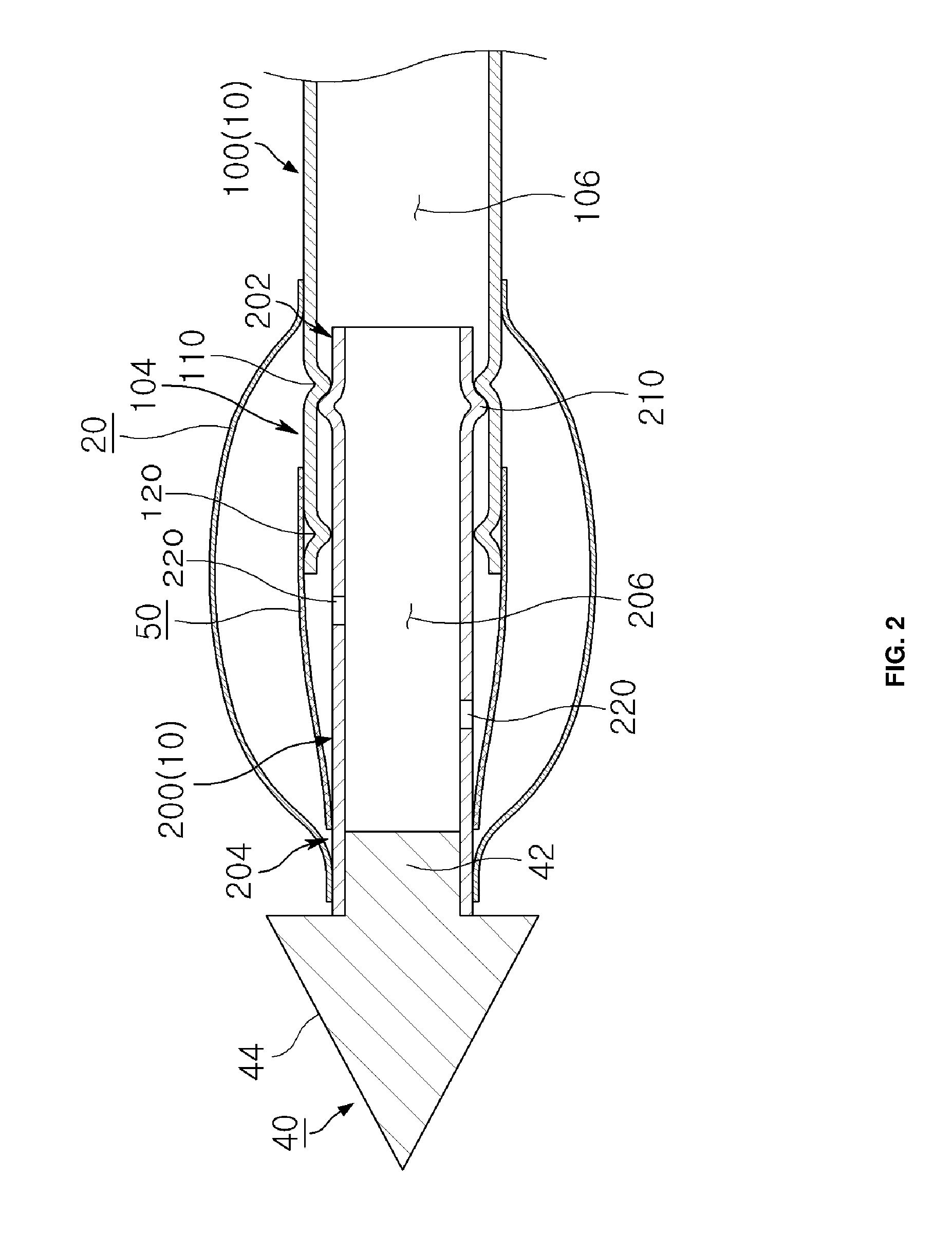
[0055]Fluid (possibly liquid) from the fluid injector is injected into the lumen (see reference numerals 106 and 206) of the catheter tube 10, is delivered from the proximal end portion 12 toward the distal end portion 14 of the catheter tube 10 through the lumen of the catheter tube 10, and is discharged through the through-holes 220 to enter the balloon 20. The balloon 20 is inflated due to the action of fluid provided as described above, and the length of the catheter tube 10 increases through the relative movement of the first tube 100 and the second tube 200 depending on the amount of the inflation of the balloon 20 (see FIG. 3). Consequently, in the balloon catheter according to the present invention, even if fluid having an excessive amount of pressure is applied to the balloon 20, the length of the catheter tube 10 can be increased through the relative movement of the first tube 100 and the second tube 200, thereby preventing the balloon 20 from being deformed to an abnormal...

second embodiment

[0066]As illustrated in FIGS. 8 and 9, the balloon catheter according to the present invention includes a catheter tube 10A having a proximal end portion 12A, a distal end portion 14A, and a lumen. The balloon catheter also includes a balloon 20A disposed on the distal end portion 14A of the catheter tube 10A, a connector 30A coupled to the proximal end portion 12A of the catheter tube 10A, and a guide wire 40A inserted into the catheter tube 10A to reinforce the strength of the catheter tube 10A.

[0067]The catheter tube 10A is elongated. The catheter tube 10A is formed as a tube, with opposite ends thereof being open, such that the proximal end portion 12A and the distal end portion 14A of the catheter tube 10A are open. The inner passage between the proximal end portion 12A and the distal end portion 14A of the catheter tube 10A forms the lumen.

[0068]The catheter tube 10A may be formed of a synthetic resin, such as polymer. The material of the catheter tube 10A is not limited there...


PUM


Abstract

The present invention provides a balloon catheter comprising: an elastic catheter tube in which a second tube is slidably inserted into a first tube; and an elasticity restriction means for restricting the elasticity of the catheter tube with an elasticity rate thereof by connecting the first tube and the second tube, or a balloon catheter in which an inflation lumen and a guide wire lumen of a catheter tube are integrated.

Description

REFERENCE TO RELATED APPLICATIONS[0001]This is a continuation of pending International Patent Application PCT / KR2014 / 010801 filed on Nov. 11, 2014, which designates the United States and claims priority of Korean Patent Applications No. 10-2013-0136166 and 10-2013-0136167 both filed on Nov. 11, 2013, the entire contents of which are incorporated herein by reference.FIELD OF THE INVENTION[0002]The present invention generally relates to a medical balloon catheter.BACKGROUND OF THE INVENTION[0003]In general, a balloon catheter applicable for medical uses includes a catheter tube having a lumen extending in the longitudinal direction between opposite ends thereof, a balloon connected to one end of the catheter tube, and a connector connected to the other end of the catheter tube. A fluid injector, such as a syringe, is connected to the connector. The balloon catheter like this is configured such that fluid (possibly liquid) injected into the lumen of the catheter tube from the fluid inj...

Claims


Application Information

Patent Timeline
IPC IPC(8): A61M25/10A61M25/00
CPCA61M25/10184A61M25/0082A61M2025/1093A61B17/8855A61B17/1617A61M25/0097A61M25/1006
Inventor AHN, YONG CHUL
Owner AHN YONG CHUL
Why Eureka
Try Eureka