
Method of fabricating semiconductor device

a semiconductor device and fabrication method technology, applied in the direction of semiconductor devices, basic electric elements, electrical appliances, etc., can solve the problem of increasing the short channel effect of transistors

Active Publication Date: 2016-08-25
SAMSUNG ELECTRONICS CO LTD
View PDF3 Cites 48 Cited by
  • Summary
  • Abstract
  • Description
  • Claims
  • Application Information

AI Technical Summary

Benefits of technology

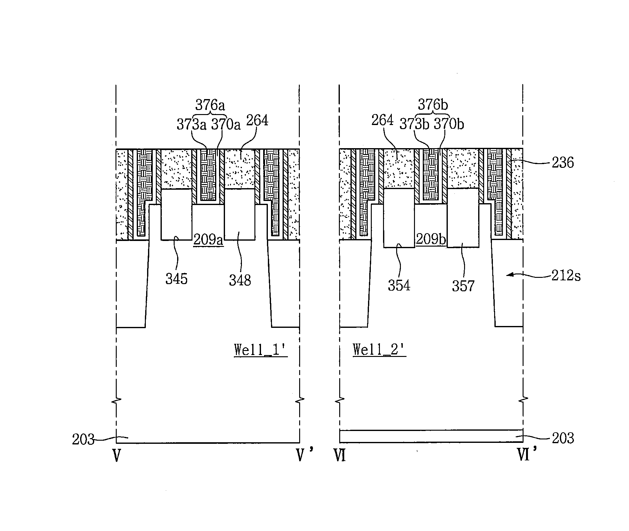
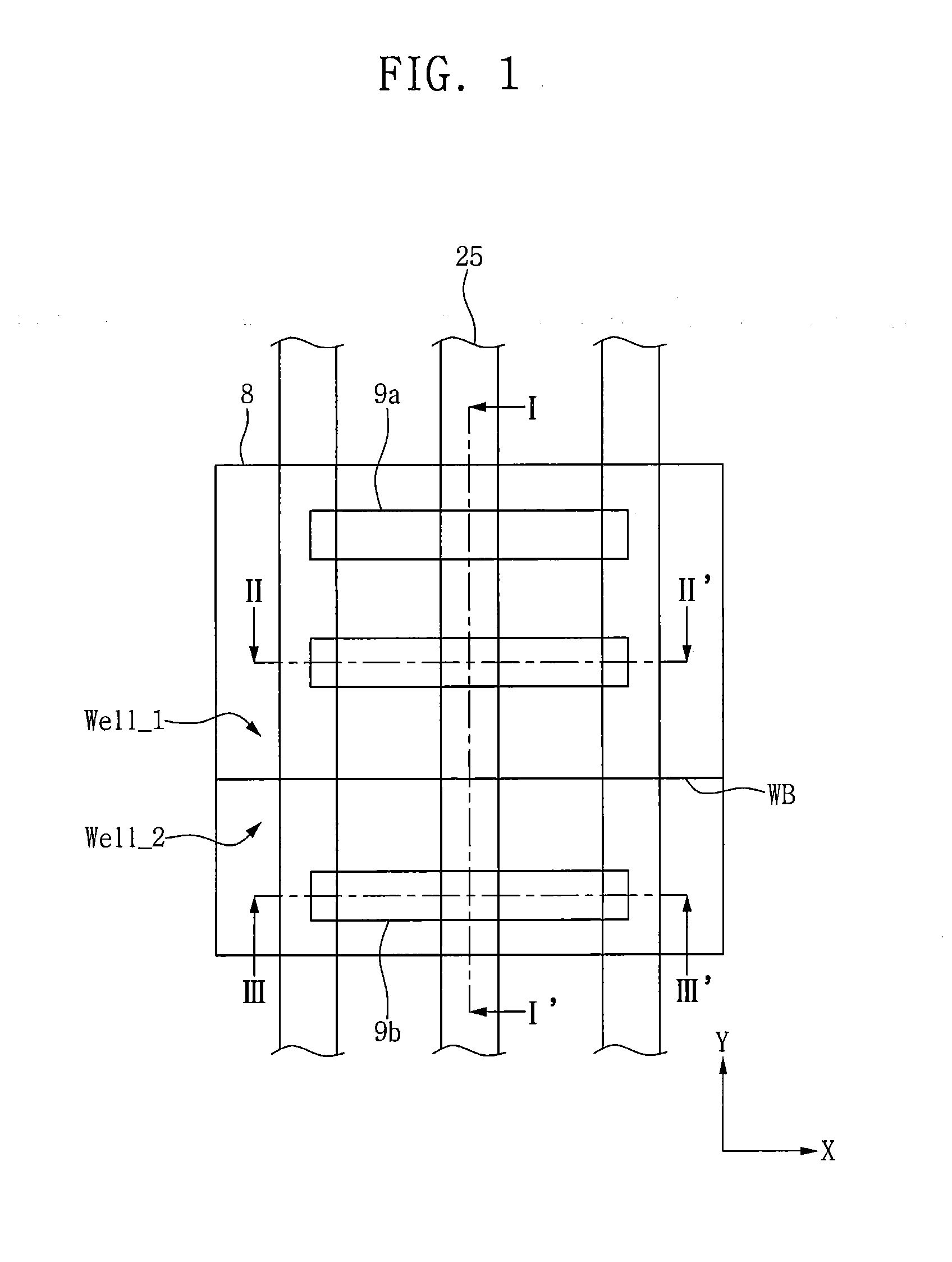
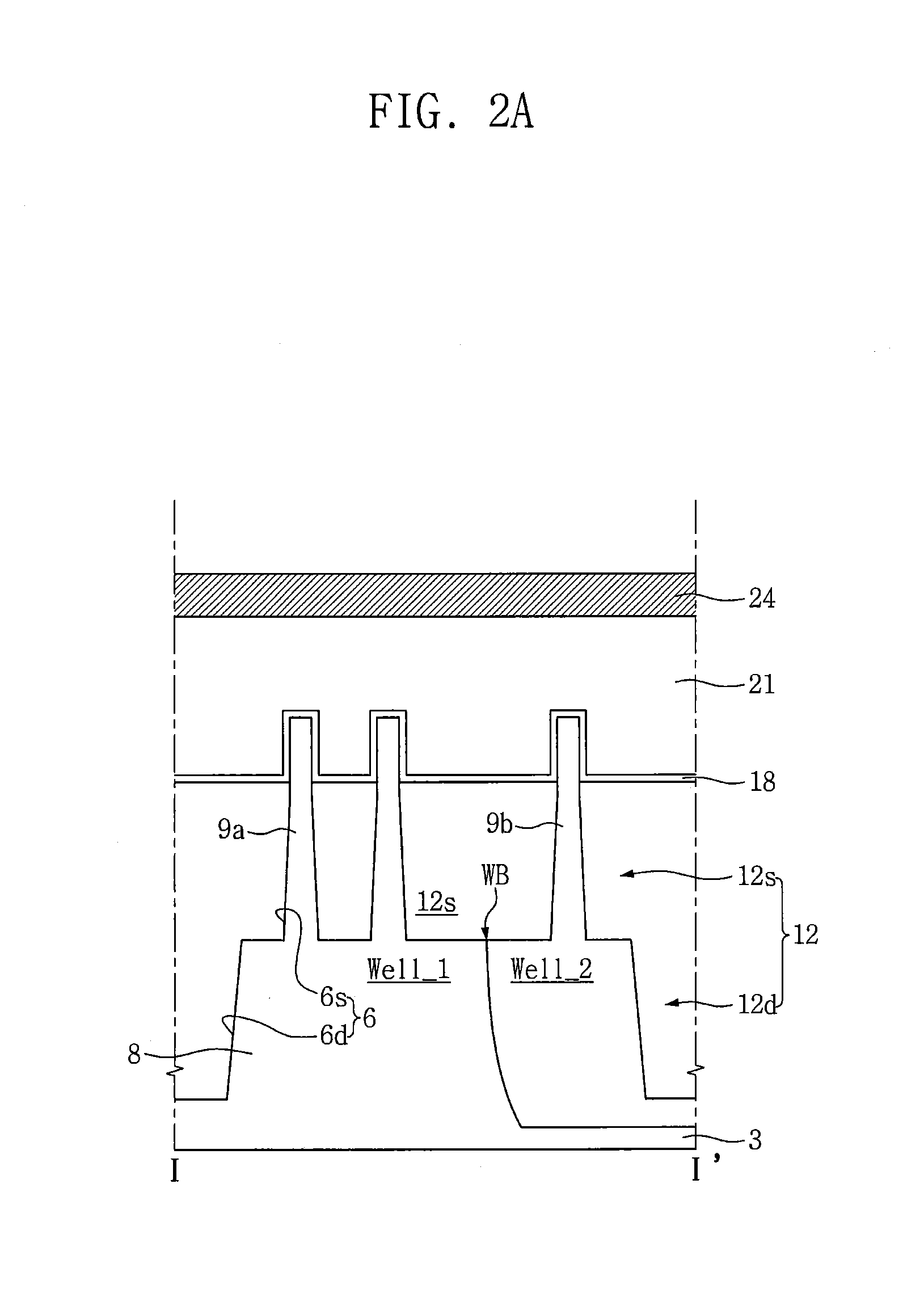
The patent describes a method of fabricating a semiconductor device by forming fin-shaped active regions in a substrate, and a well boundary region between them. A sacrificial gate layer and a hardmask pattern are sequentially patterned to define hardmask patterns and a gate cut region. An interlayer insulating layer is formed on the hardmask pattern and the sacrificial gate layer. A second etching mask pattern is formed on the interlayer insulating layer to form active recess areas in the fin-shaped active regions. The method allows for precise placement of the gate cut region and the formation of separate gate electrodes for NMOS and PMOS devices.

Problems solved by technology

Such NMOS transistors and PMOS transistors may be scaled down as semiconductor devices become more highly integrated, and accordingly, short channel effects in transistors may increasingly result.
However, unexpected problems caused by arranging FinFET NMOS transistors and FinFET PMOS transistors having reduced sizes in a limited space may occur in manufacturing processes.

Method used


Image

  • Method of fabricating semiconductor device
  • Method of fabricating semiconductor device
  • Method of fabricating semiconductor device

Examples


Embodiment Construction

[0024]Various embodiments will now be described more fully with reference to the accompanying drawings in which some embodiments are shown. These inventive concepts may, however, be embodied in different forms and should not be construed as limited to the embodiments set forth herein. Rather, these embodiments are provided so that this disclosure is thorough and complete and fully conveys the inventive concepts to those skilled in the art. Accordingly, all such modifications are intended to be included within the scope of these inventive concepts as defined in the claims. Like numerals refer to like elements throughout the specification.

[0025]Embodiments are described herein with reference to cross-sectional and / or planar illustrations that are schematic illustrations of idealized embodiments and intermediate structures. As such, variations from the shapes of the illustrations as a result, for example, of manufacturing techniques and / or tolerances, are to be expected. Thus, embodime...


PUM


Abstract

A method of fabricating a semiconductor device includes forming a first well region and a second well region in a semiconductor substrate, forming an isolation region defining a first fin active region and a second fin active region on the semiconductor substrate, forming a sacrificial gate layer on the semiconductor substrate having the first and second fin active regions and the isolation region, forming a hardmask line on the sacrificial gate layer, forming a gate cut mask having a gate cut opening on the hardmask line, and forming first and second hardmask patterns spaced apart from each other by etching the hardmask line using the gate cut mask as an etching mask. The gate cut opening overlaps a boundary between the first and second well regions formed between the first and second fin active regions, and has a line shape in a direction intersecting the hardmask line.

Description

CROSS-REFERENCE TO RELATED APPLICATION[0001]This application claims priority under 35 U.S.C. §119 to Korean Patent Application No. 10-2015-0025302 filed on Feb. 23, 2015, the disclosure of which is hereby incorporated by reference in its entirety.BACKGROUND[0002]1. Technical Field[0003]Embodiments of the inventive concepts relate to methods of fabricating a semiconductor device, structures of the semiconductor device, and electronic systems including the semiconductor device.[0004]2. Description of Related Art[0005]Discrete devices, such as NMOS transistors and PMOS transistors, may be used in integrated circuits of semiconductor devices. Such NMOS transistors and PMOS transistors may be scaled down as semiconductor devices become more highly integrated, and accordingly, short channel effects in transistors may increasingly result. A FinFET structure has been proposed to reduce or suppress short channel effects in transistors. However, unexpected problems caused by arranging FinFET ...

Claims


Application Information

Patent Timeline
IPC IPC(8): H01L21/8238H01L29/78H01L29/66
CPCH01L21/823821H01L21/823807H01L29/7848H01L21/823878H01L29/66545H01L21/823814H01L21/823828H01L29/7813H01L29/7831H01L29/785
Inventor YOU, JUNGGUNJEONG, SUKHOON
Owner SAMSUNG ELECTRONICS CO LTD
Learn More