Method of reducing flue gas emissions and a boiler

a technology of flue gas emission reduction and boiler, which is applied in the field of reducing flue gas emissions and a boiler, can solve the problems of difficult to create optimal conditions for sncr in several combustion apparatuses, shifting and narrowing of temperature windows, and the operation of each variation is limited to precisely determined conditions, so as to achieve efficient and more economical effects

Active Publication Date: 2016-08-25
ANDRIZ OY
View PDF14 Cites 0 Cited by
  • Summary
  • Abstract
  • Description
  • Claims
  • Application Information

AI Technical Summary

Benefits of technology

[0025]Also, a steam-generating boiler has been conceived having a water circulation system comprising heat recovery surfaces, such as superheaters, and a furnace for combusting fuel and for generating flue gases, which flue gases flow mainly upwards in the furnace and further to a superheater zone and via other heat recovery surfaces out of the boiler, and feeding means for introducing an agent for reducing nitrogen oxides in the flue gases. One or more heat exchangers are located in the flue gas flow in the furnace for decreasing the temperature of the flue gases and for creating a suitable temperature window in the flue gas flow for reducing nitrogen oxides, and that the feeding means for the reducing agent are located in the flue gas flow direction after one or more heat exchangers and prior to the superheater zone.
[0032]An advantage of the invention is that the agent reacting with NOx (e.g. ammonia or urea) can be injected in the proper temperature window in large volume, whereby an adequate retention time is obtained. The agent can be introduced e.g. entrained in air jets above a heat exchanger, such as screen, by evaporating the ammonia into the air, whereby efficient mixing is obtained simultaneously. An additional advantage worth mentioning is that the location of the screen in accordance with the invention decreases the escape of liquor particles, i.e. so-called carry over up onto the superheater surfaces.
[0035]The solution according to the invention allows lowering the height of the superheaters that typically are located above the bullnose and thus also lowering the total height of the boiler.
[0036]Obtaining the desired temperature window in the furnace of a boiler where heat is transferred mainly into the walls of the furnace only, would make the furnace of the boiler, and thus whole boiler and the boiler plant very high.
[0039]The present invention allows e.g. feeding the injected reducing agent, such as urea and / or ammonia together with a medium, e.g. air or circulated flue gas, effectively in the furnace upstream of the superheaters, which thus will be better protected against possible corrosive effect of the SNCR-agent. Feeding of the reducing agent together with combustion air of the boiler is advantageous, because then there is no need to provide the boiler with additional openings for feeding said agent. The carrier gas for the reducing agent can originate from the boiler's combustion air system or a separate dedicated gas source. The flue gas used as carrier gas can originate from a boiler wherein the invention is applied or from another boiler at the mill.
[0042]The present invention provides a simple method of controlling the emissions of detrimental nitrogen oxide compounds from combustion processes.

Problems solved by technology

The operation of each variation is limited to precisely determined conditions.
However, carbon monoxide is present in almost all processes utilizing the SNCR-method, and the detrimental result thereof is shifting and narrowing of temperature windows.
Optimal conditions for SNCR are hard to create in several combustion apparatuses.
However, in this patent no attention has been paid to creating a suitable temperature window between nitrogen oxide and the reducing agent.
By means of these techniques, a NOx-reduction of 30-50% has been reached, but in practice they require adjustments that are not optimal for a recovery boiler.
Often these techniques require oversized furnaces for keeping the temperature after the furnace adequately low and / or more expensive material solutions for preventing corrosion.
In practice staged combustion or SNCR-technique in recovery boilers requires temperatures even as low as 850-1000° C., which are reached only in such recovery boilers that are bigger and thus more expensive than conventional boilers.

Method used


Image

  • Method of reducing flue gas emissions and a boiler
  • Method of reducing flue gas emissions and a boiler
  • Method of reducing flue gas emissions and a boiler

Examples


Embodiment Construction

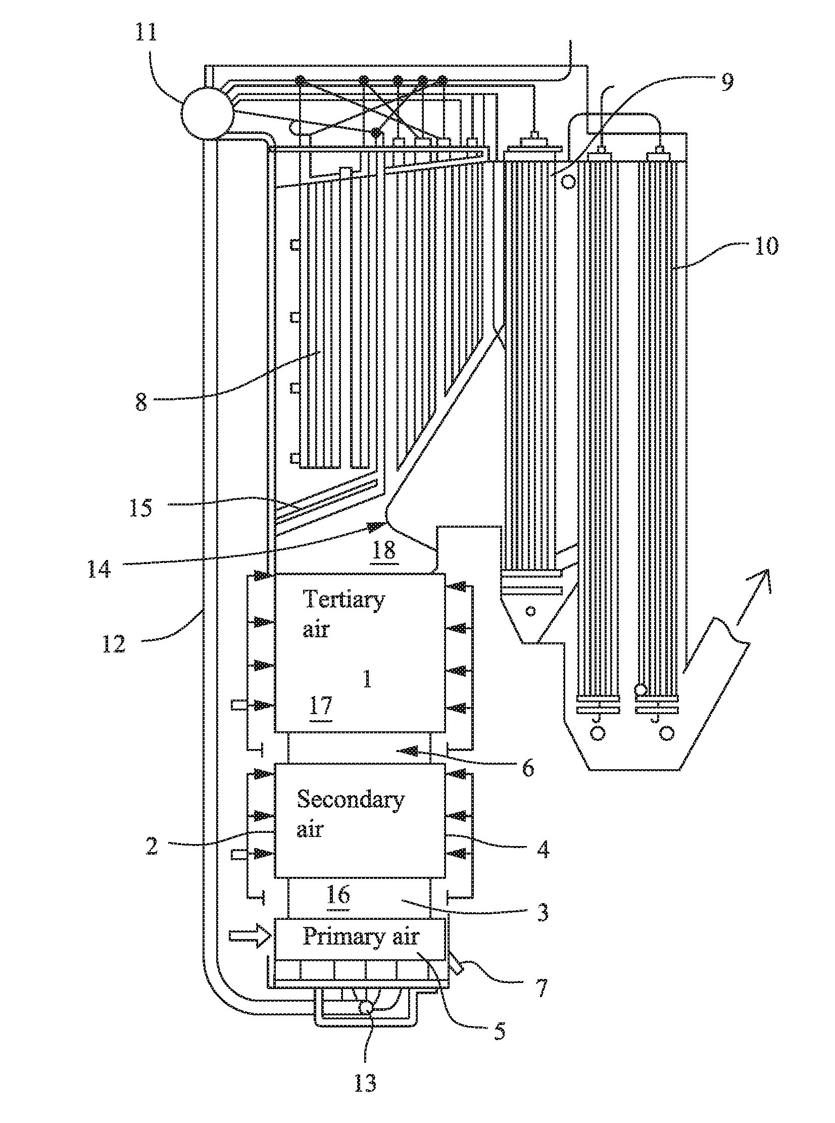
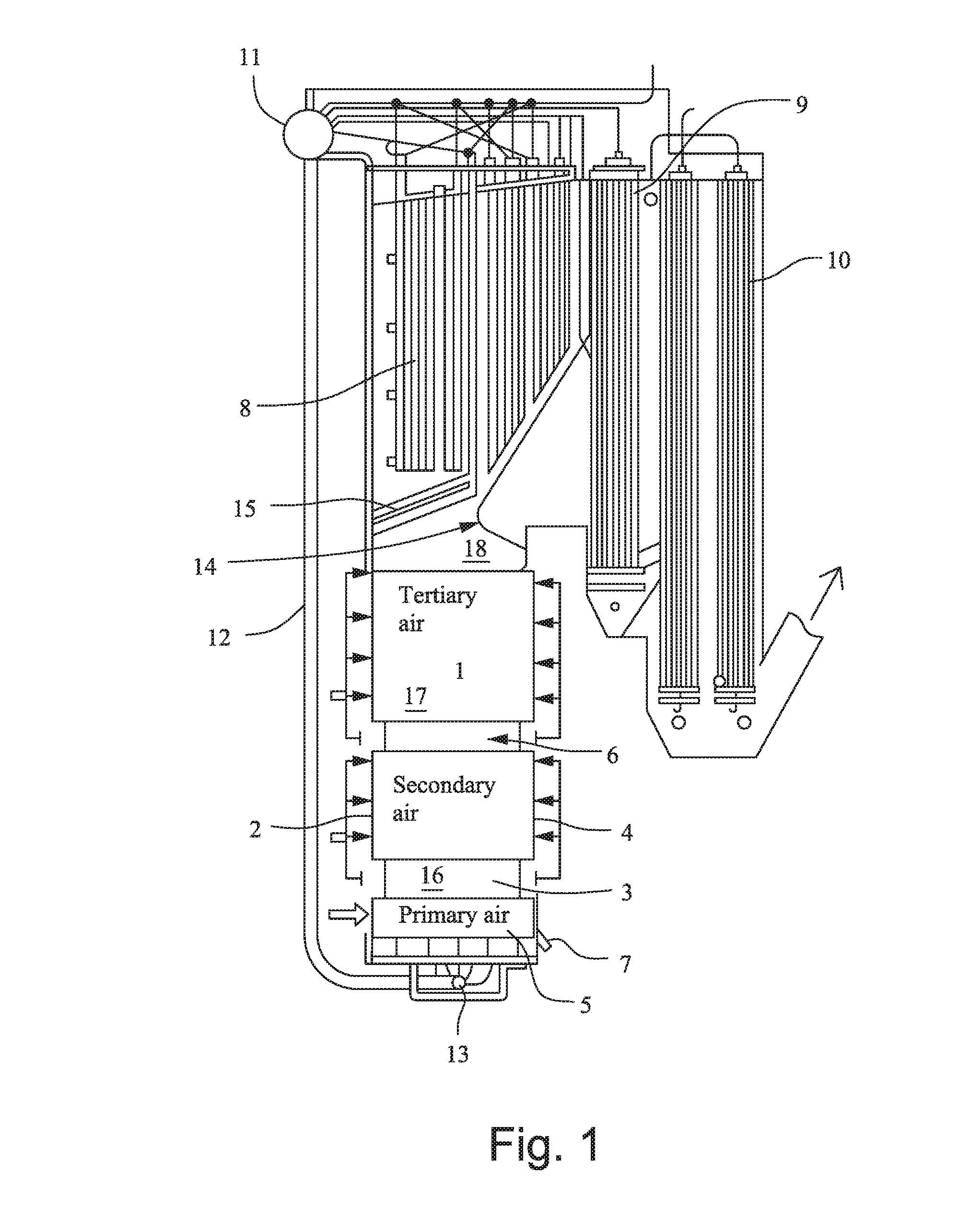
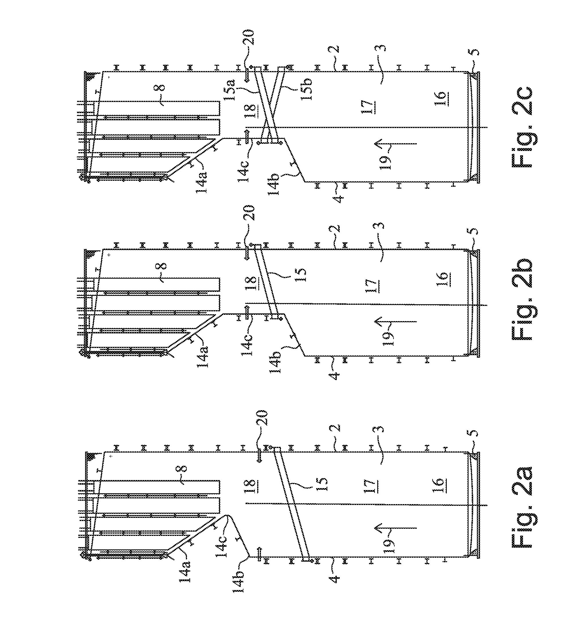
[0047]FIGS. 2a-2c illustrate the construction of a recovery boiler having a furnace defined by water tube walls: a front wall 2, side walls 3 and a rear wall 4, as well as a bottom 5 formed of water tubes. Superheaters 8 of the boiler are located above the furnace.

[0048]A lower part 16 of the furnace, where the combustion of waste liquor mainly takes place.

[0049]A middle part 17 of the furnace, where the final combustion of gaseous combustible substances mainly takes place.

[0050]An upper part 18 of the furnace

[0051]A superheater area 8, wherein the saturated steam exiting the steam drum is heated into (superheated) steam having a higher temperature. A so-called screen tube system 15 is provided in the flue gas flow direction upstream of the superheater zone above the bullnose.

[0052]Flue gas generated in the furnace flows upwards into the upper part of the furnace and further to other heat recovery parts of the boiler, such as superheaters 8. The main flow direction of the flue gas i...


PUM

PropertyMeasurementUnit
temperatureaaaaaaaaaa
temperaturesaaaaaaaaaa
temperatureaaaaaaaaaa

Abstract

A method and a boiler for decreasing the amount of nitrogen oxides in flue gases of a boiler, which flue gases are generated in the combustion of fuels and air. The boiler has a water circulation system comprising superheaters and a furnace for combustion of fuel and for generating flue gases that contain nitrogen oxides, which flue gases mainly flow upwards in the furnace and further to the superheater zone and via other heat recovery surfaces of the boiler out of the boiler, and a nitrogen oxides reducing agent is introduced into the flue gases. The nitrogen oxides reducing agent is introduced into the flue gases prior to the superheater zone, after the temperature of the flue gases is decreased by at least one heat exchanger that is located upstream of the nose of the boiler and upstream of the introduction of the nitrogen oxides reducing agent.

Description

RELATED APPLICATIONS[0001]This application is a divisional of U.S. application Ser. No. 13 / 264,516, (now U.S. Pat. No. 9,310,075), which is the U.S. national phase of International Application No. PCT / FI2010 / 050298 filed 14 Apr. 2010 which designated the U.S. and claims priority to Finnish Patent Application No. 20090141 filed 15 Apr. 2009, the entirety of these applications are incorporated by reference.BACKGROUND OF INVENTION[0002]The present invention relates to a method of decreasing an amount of nitrogen oxides from flue gases of a boiler, which nitrogen oxides are generated in the combustion of fuels and air or other oxygen-containing gas. The invention also relates to a steam-generating boiler.[0003]Flue gases of steam-generating boilers, such as a recovery boiler of a chemical pulp mill, are led from the furnace into contact with various heat exchangers, superheaters, boiler bank and water preheaters of the boiler, whereby the heat contained in the gases is recovered in the ...

Claims


Application Information

Patent Timeline
Patent Type & Authority Applications(United States)
IPC IPC(8): F23J15/00F22B21/40F22B21/34
CPCB01D53/56B01D2251/2062B01D2251/2067F23J2215/101F22B21/40F23G2209/101F23J15/003F22B21/341Y02P80/15Y02E20/12F22B31/045F22D1/02
Inventor MIIKKULAINEN, PASIPAKARINEN, LAURI
Owner ANDRIZ OY
Why Eureka
Try Eureka