Apparatus comprising a functional component likely to be thermally overloaded during the operation thereof and a system for cooling the component

Active Publication Date: 2016-08-11
COMMISSARIAT A LENERGIE ATOMIQUE ET AUX ENERGIES ALTERNATIVES +1
View PDF25 Cites 6 Cited by
  • Summary
  • Abstract
  • Description
  • Claims
  • Application Information

AI Technical Summary

Benefits of technology

The patent text is saying that there is a best way to cool down a Peltier module so that it works better. If the thermal resistance is too low, the hot and cold faces of the module touch and cause short circuits. If the thermal resistance is too high, the component gets too hot and doesn't cool down when there's no current passing through it. The technical effect of this patent text is to help R&D personnel understand how to cool down a Peltier module optimally for better performance.

Problems solved by technology

However, it has already been demonstrated that, in certain electrical devices into which they have been integrated, these power components are liable to intermittently be subjected to electrical overloads and therefore to surplusses in electrical power and hence in heat to be removed.
However, to do so would grossly over-dimension the complete cooling system, as the intrinsic volume of the supplementary heat sink would be considerable, typically equal to that of the nominal heat sink.
However, the hot face of a thermoelectric module would release a very large quantity of heat in the event of large heat peaks.
The efficiency of a thermoelectric module used alone is therefore limited to thermal powers to be removed which remain relatively low.
However, this is not possible in the case where substantial thermal powers are to be removed, as, in this case, the overheating temperature reached by the component gets considerably higher than the melting point of the PCM material since it is not able to rapidly absorb the thermal overload.
A system such as this is not suitable for absorbing spikes of thermal power from the source, as the first thermal switch only directs the heat released by the source to the PCM material so as to achieve the phase change thereof.
Here, no actual storage of heat is possible and the system described is not able to absorb spikes of thermal power.

Method used


Image

  • Apparatus comprising a functional component likely to be thermally overloaded during the operation thereof and a system for cooling the component
  • Apparatus comprising a functional component likely to be thermally overloaded during the operation thereof and a system for cooling the component
  • Apparatus comprising a functional component likely to be thermally overloaded during the operation thereof and a system for cooling the component

Examples


Embodiment Construction

[0049]Other advantages and features of the invention will become more clearly apparent upon reading the detailed description of the invention, given by way of non-limiting illustration with reference to the following figures in which:

[0050]FIG. 1 is a diagrammatic perspective view of a device comprising an electronic component and the cooling system thereof according to the prior art;

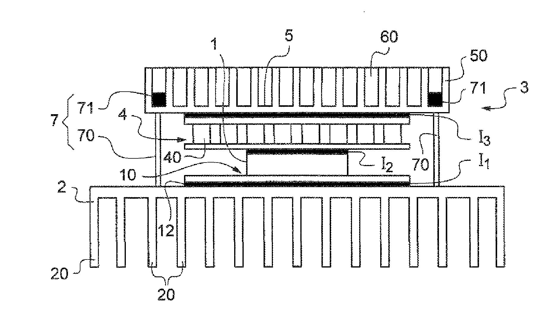
[0051]FIG. 2 is a diagrammatic perspective view of a device comprising a power electronic component and the cooling system thereof, according to the invention;

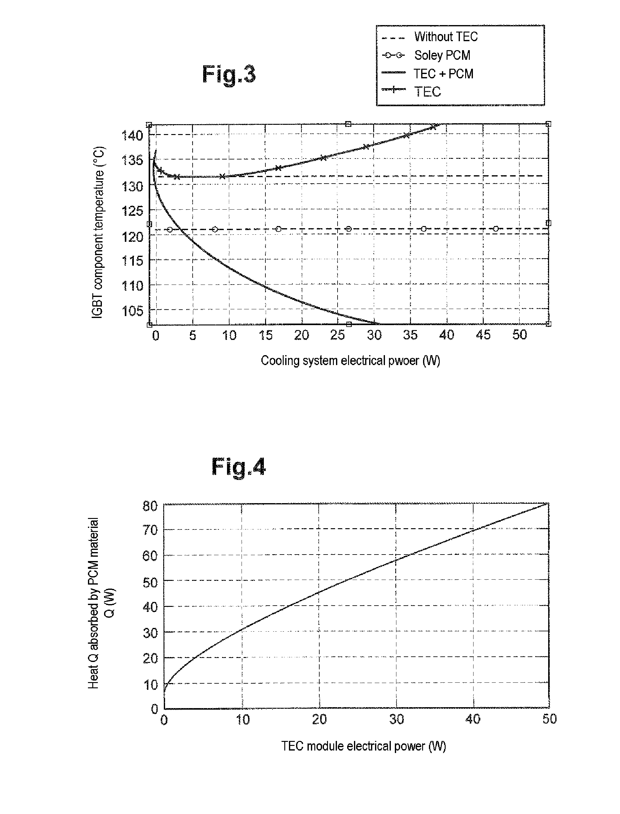
[0052]FIG. 3 shows the variation in the temperature of the junctions of a power component as a function of the electrical power used by the cooling system dedicated thereto in various configurations, namely respectively a system according to the prior art with solely one heat sink and no thermoelectric module and no PCM material; a system according to the prior art comprising a heat sink and solely one PCM material; a system according to the prior...


PUM


Abstract

The invention relates to an apparatus comprising a functional component likely to be thermally overloaded during the operation thereof, and a system for cooling the component, comprising: a thermoelectric module comprising a cold surface and a hot surface, the cold surface being thermally coupled with the component; a heat sink thermally coupled with the hot surface of the module, the heat sink including an exchange surface with the surrounding environment and at least one cell containing a phase-change material (PCM), the PCM material contained in the cell or cells being suitable for melting when the heat released from the cold surface of the module is that of the thermally overloaded component, the exchange surface being suitable for bringing the PCM material from the molten phase to the solid phase thereof when the heat released from the cold surface of the module is that of the operational component which is not thermally overloaded.

Description

TECHNICAL FIELD[0001]The present invention relates to a device comprising a functional component liable to be thermally overloaded during the operation thereof and to a system for cooling the component.[0002]The invention pertains to the production of an improved cooling system which, while being of limited size, allows thermal overloading of the component to be absorbed.[0003]Although described with reference to the application of cooling power electronics components, the invention is equally applicable to the cooling of any functional component liable to be thermally overloaded during the operation thereof over periods of up to a few tens of minutes. Thus, the functional component may be a computer, a microprocessor, or a hot plate for which it is sought to absorb temperature overrun when a PID (“proportional-integral-derivative”) controller is used for temperature control.[0004]It is specified that in the context of the invention, “functional component” is understood to mean a si...

Claims


Application Information

Patent Timeline
IPC IPC(8): H01L23/38H01L23/427H01L23/373H01L23/367
CPCH01L23/38H01L23/4275H01L2924/0002H01L23/427H01L23/3737H01L23/3672H01L23/3675H01L23/373H01L2924/00
Inventor CAROFF, TRISTANRADOSLAVA, MITOVASIMON, JULIA
Owner COMMISSARIAT A LENERGIE ATOMIQUE ET AUX ENERGIES ALTERNATIVES
Why Eureka
Try Eureka