
Methods for meeting localized peak loads in buildings and urban centers

a technology for urban centers and buildings, applied in indirect heat exchangers, lighting and heating apparatuses, heating types, etc., can solve the problems of increasing the pressure drop, many difficulties encountered in real life, and inability to obtain a sharp fron

Active Publication Date: 2016-08-11
RES FOUND THE CITY UNIV OF NEW YORK
View PDF10 Cites 6 Cited by
  • Summary
  • Abstract
  • Description
  • Claims
  • Application Information

AI Technical Summary

Benefits of technology

This patent describes a method for managing the heat storage capability of buildings to meet peaks in energy demand. The method involves circulating air through a thermal bed that has stored heat to absorb the air and heat it up. The heated air is then circulated to the building to provide energy for heating or cooling. The method allows for efficient storage and discharge of heat for short or long periods of use. Overall, the patent provides a technical solution for managing thermal energy in buildings to improve their energy efficiency.

Problems solved by technology

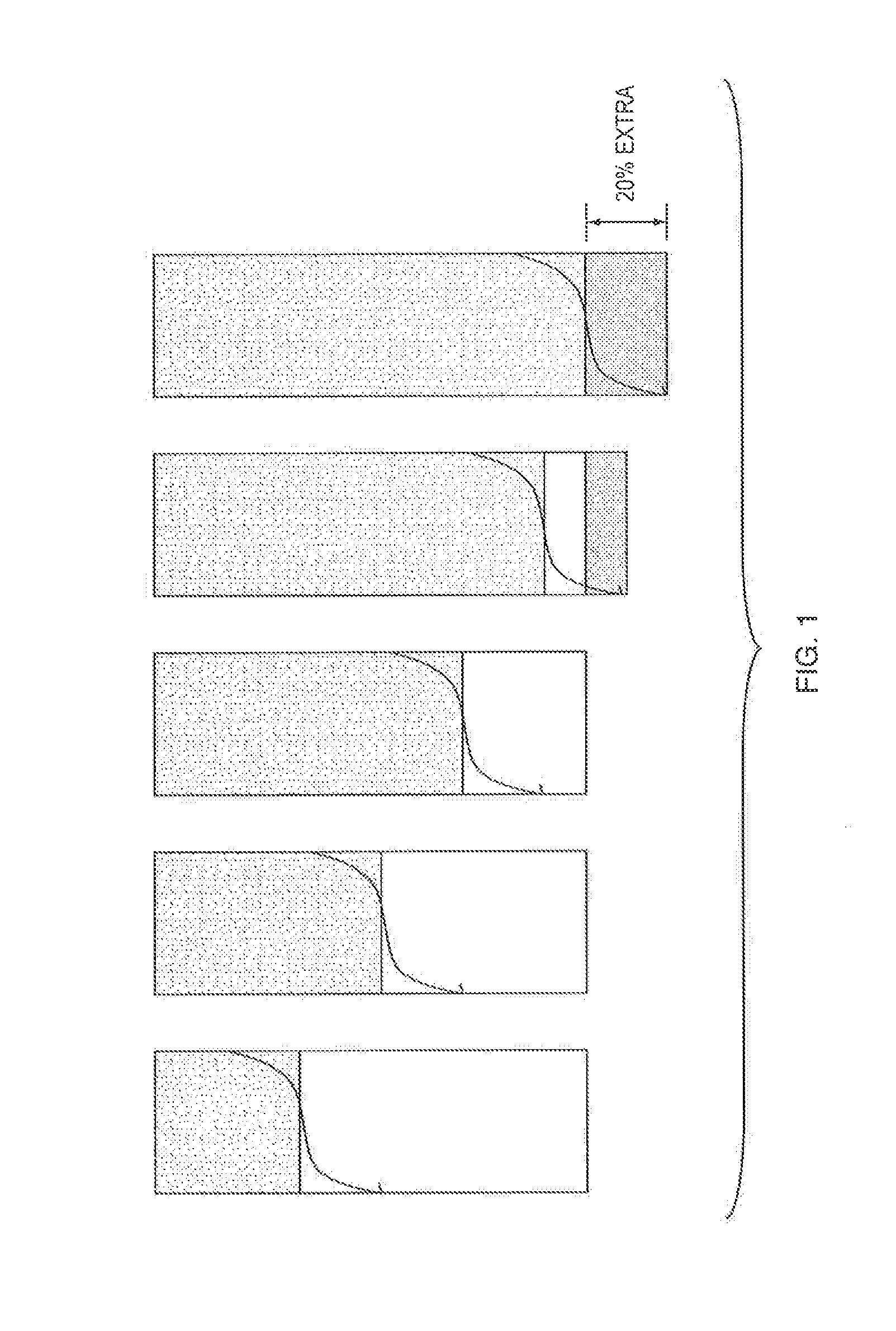
However, many difficulties are encountered in real life to achieve such sharp front.
However, many systems, it is not feasible to obtain a sharp front.
But this method will largely increase the pressure drop incurred which will increase the operating costs, particularly for the case of gases as the carrier medium.
Therefore, if fractional utilization is increased, compression costs increase as well.
However for not so sharp fronts and high pressure drop systems this design of a regular packed bed arrangement is not optimal.
In fact for some applications such as flue gas treatment, higher pressure drops are not allowed so the overall fractional utilization is increased and systems become expensive.
In large urban areas, which have non-uniform weather patterns, often the grid electricity load demand is highly skewed.
This type of additional infrastructure increases the cost of energy supplied and the extra cost is passed onto the consumers.

Method used


Image

  • Methods for meeting localized peak loads in buildings and urban centers
  • Methods for meeting localized peak loads in buildings and urban centers
  • Methods for meeting localized peak loads in buildings and urban centers

Examples


Embodiment Construction

[0019]The following detailed description is of the best currently contemplated modes of carrying out these teachings. The description is not to be taken in a limiting sense, but is made merely for the purpose of illustrating the general principles of these teachings, since the scope of these teachings is best defined by the appended claims. Although the teachings have been described with respect to various embodiments, it should be realized these teachings are also capable of a wide variety of further and other embodiments within the spirit and scope of the appended claims.

[0020]As used herein, the singular forms “a,”“an,” and “the” include the plural reference unless the context clearly dictates otherwise.

[0021]Except where otherwise indicated, all numbers expressing quantities of ingredients, reaction conditions, and so forth used in the specification and claims are to be understood as being modified in all instances by the term “about.” Accordingly, unless indicated to the contra...


PUM


Abstract

A method to use high temperature thermal storage for integration into building heating / cooling systems and to meet building's peak power demand. The method can be used to store the thermal energy at any desirable rate and then discharge this stored energy to meet the demand for short or long time intervals. Input energy stored with this method is thermal energy, however, output can be thermal or electric based upon the requirement.

Description

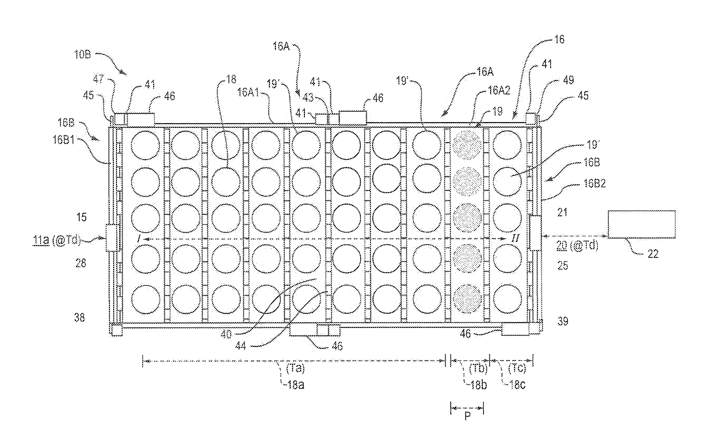
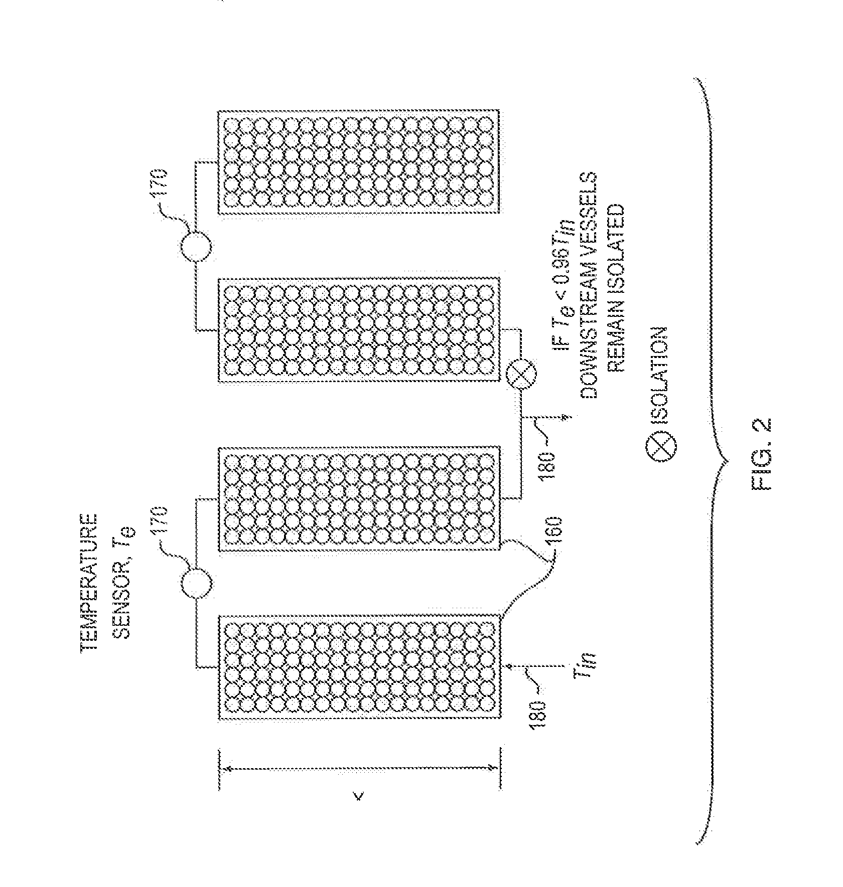
BACKGROUND[0001]Packed beds have been utilized for various heat and mass transfer operations, e.g. adsorption, thermal storage, chromatography etc. The performance of packed beds in most of these systems is analyzed using concentration or temperature profile in the bed and their progression in time. It is desirable, in many systems, to have a profile which progresses in the form of sharp front. For such a profile, the space or material utilization is maximum and recovery is very efficient. However, many difficulties are encountered in real life to achieve such sharp front. In thermal or heat storage processes, having a profile with a sharp front becomes even more important due to exergetic efficiency. Other patents have described certain ways to achieve this sharpness for thermal wave front. However, many systems, it is not feasible to obtain a sharp front. The relative steepness of the front can be increased by increasing the length of the bed traversed or connecting many such beds...

Claims


Application Information

Patent Timeline
IPC IPC(8): F24D11/00F28D15/00F28D20/00
CPCF25B17/08F24F5/0017F28D17/005F28D20/0056F24D2220/10F24D11/006F28D2020/0078Y02E60/142Y02E60/147F24D11/008F28D15/00F28D20/00F28D2020/0017Y02B30/62Y02E60/14Y02A30/27Y02A30/60F28D2020/0065
Inventor KAWAJI, MASAHIROBINDRA, HITESH
Owner RES FOUND THE CITY UNIV OF NEW YORK
Learn More