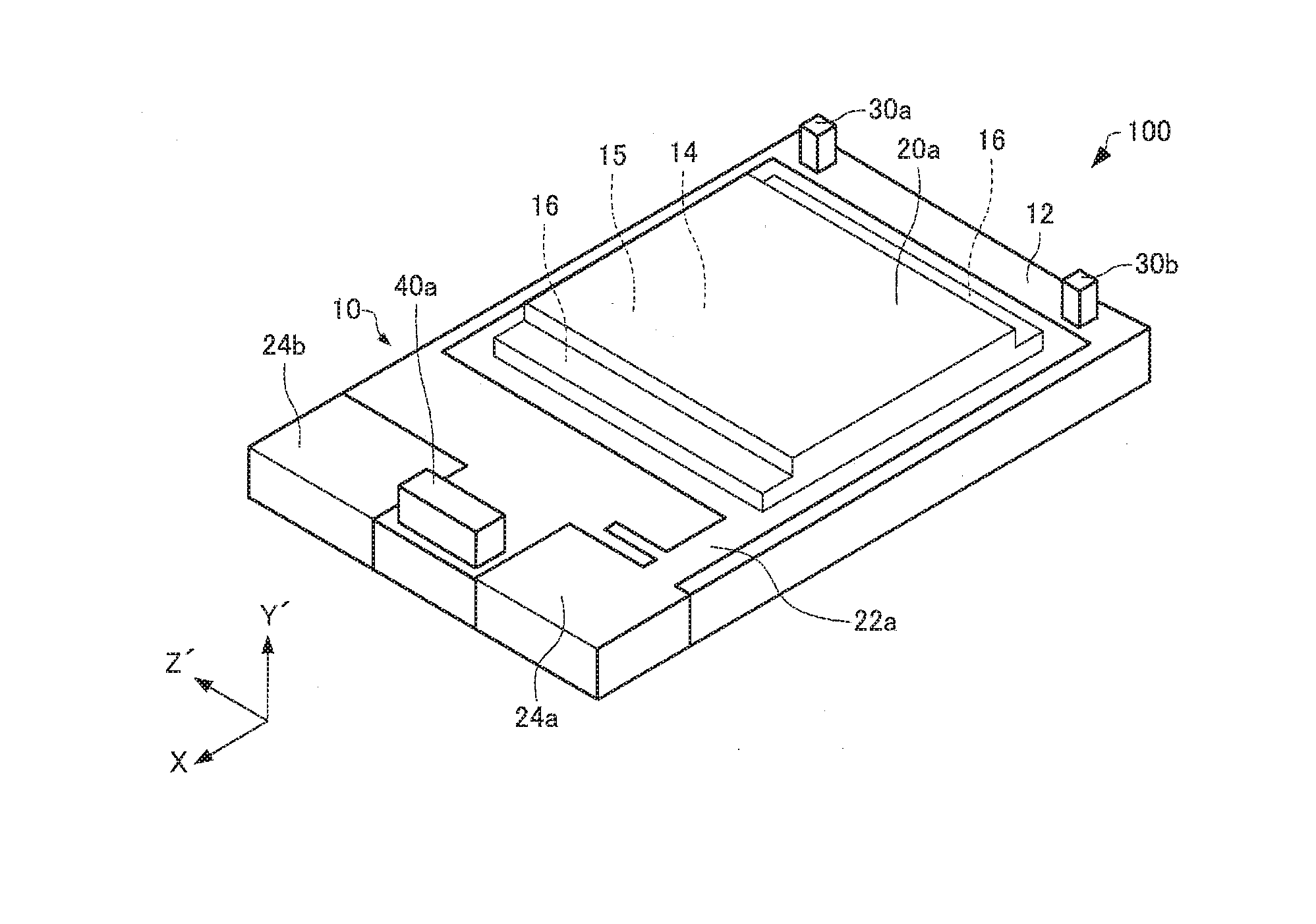
Resonator element, resonator, resonator device, oscillator, electronic apparatus, and moving object
a resonator and element technology, applied in the direction of oscillators, electrical apparatus, oscillators, etc., can solve the problems of deterioration of electric characteristics of resonator elements in some cases, and achieve the effect of reducing the deterioration of electric characteristics
- Summary
- Abstract
- Description
- Claims
- Application Information
AI Technical Summary
Benefits of technology
Problems solved by technology
Method used
Image
Examples
experimental example
3. Experimental Example
[0115]Hereinafter, the invention will be described more specifically according to an experimental example. The invention is not limited to the following experimental example.
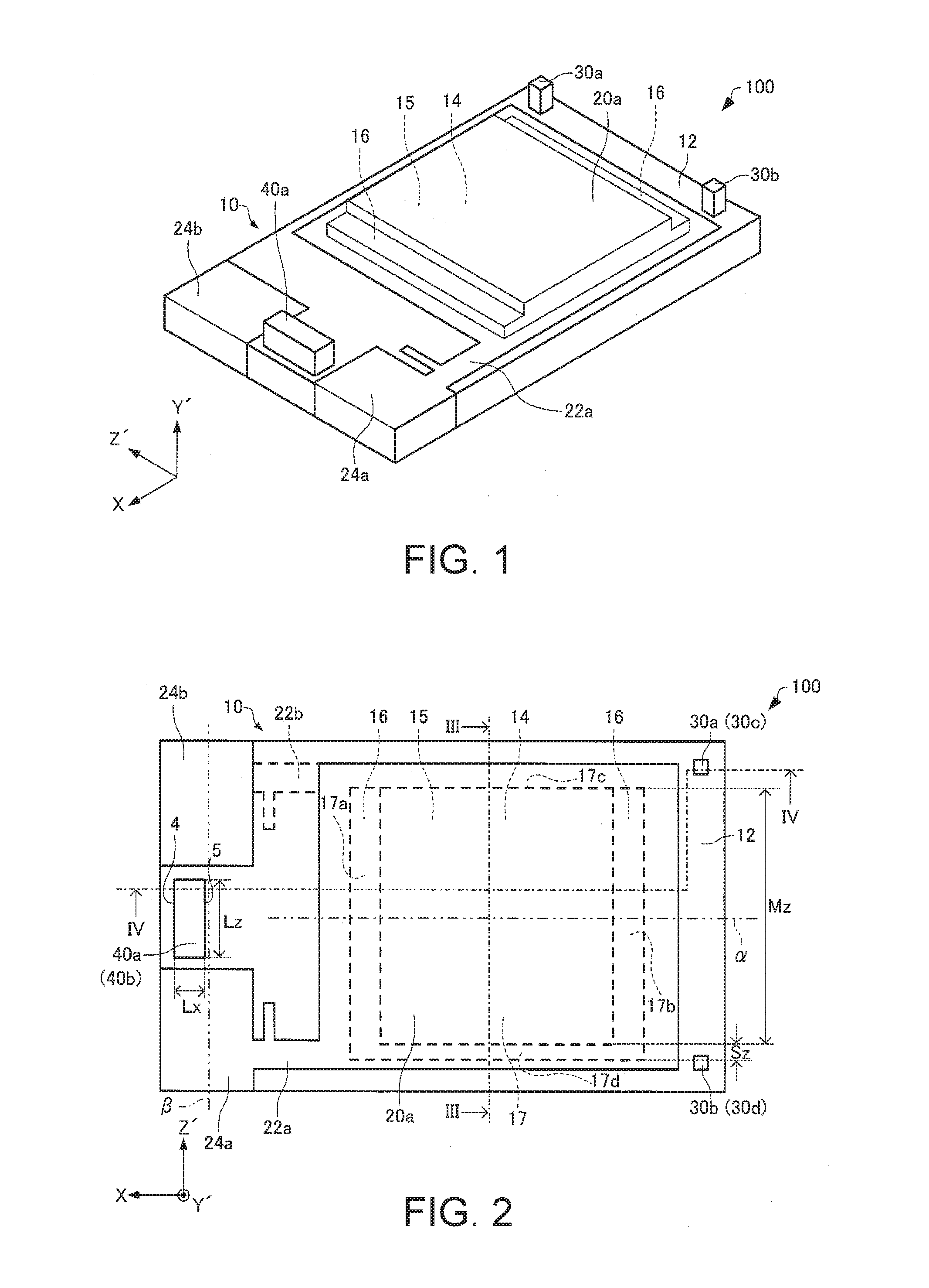
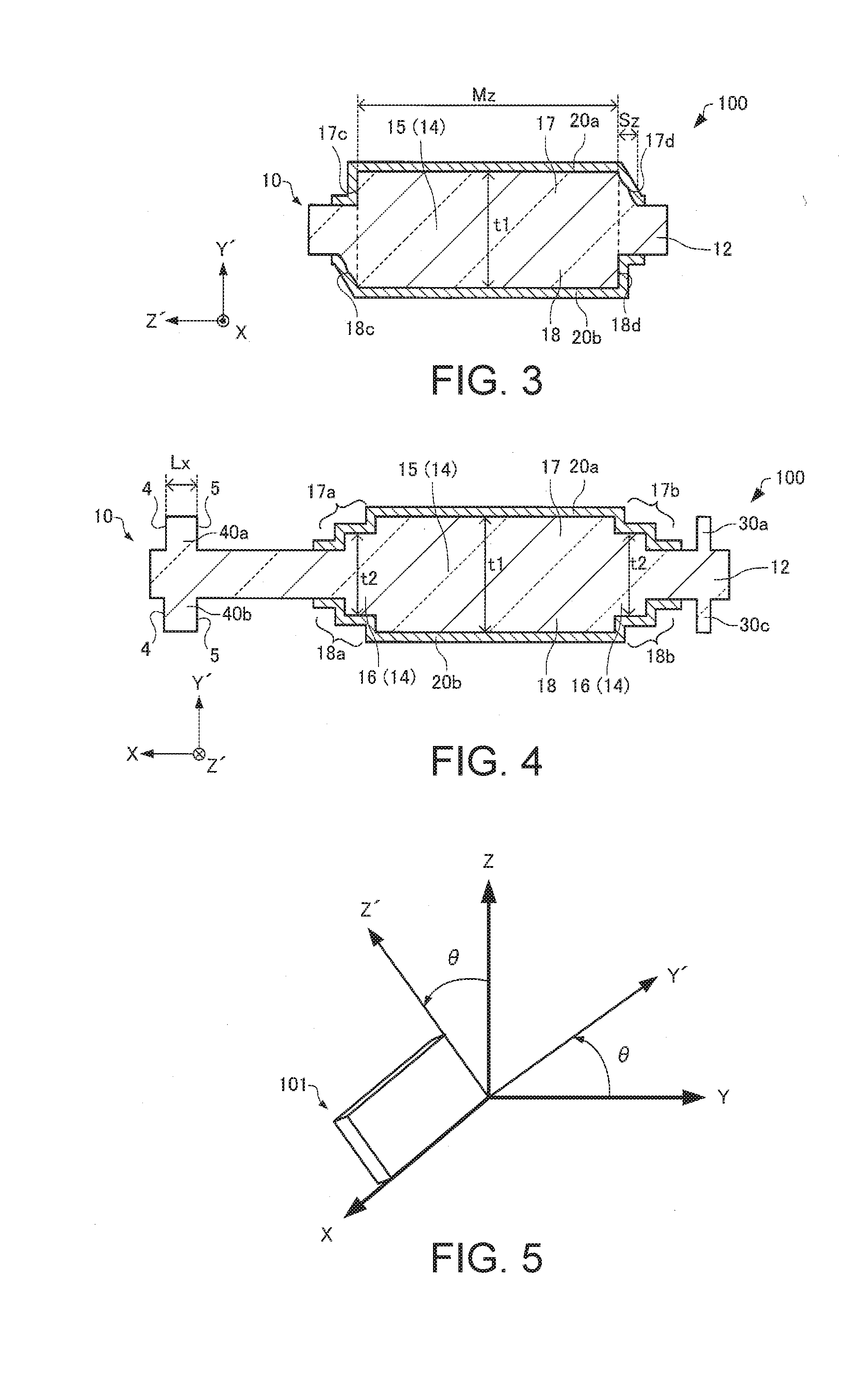
[0116]In the experimental example, the same resonator element as the above-described resonator element 200 was manufactured. Specifically, the resonator element in which the length of the quartz crystal substrate 10 along the X axis was about 1 mm, the length of the quartz crystal substrate 10 along the Z′ axis was about 0.6 mm, and the resonance frequency was about 26 MHz was manufactured. In the resonator element, a CI value was measured by changing the length Lz of the first protrusions 40a and 40b along the Z′ axis and the length Mz of the vibration section 14 along the Z′ axis. The dimensions Lz and Mz were measured by a dimension measurement device and the CI value was measured using a network analyzer.
[0117]FIG. 12 is a graph illustrating a relation between a ratio (Lz / Mz) of Lz to ...
first modification example
6.1. First Modification Example
[0136]Next, a resonator device according to a first modification example of the embodiment will be described with reference to the drawing. FIG. 16 is a sectional view schematically illustrating a resonator device 900 according to the first modification example of the embodiment.
[0137]Hereinafter, in the resonator device 900 according to the first modification example of the embodiment, the same reference numerals are given to elements having the same functions as the constituent elements of the above-described resonator device 800 according to the embodiment and the detailed description thereof will be omitted.
[0138]In the above-described resonator device 800, as illustrated in FIG. 15, the accommodation portion 812 that accommodates a thermosensitive element 810 is formed by forming a frame-shaped member 814 on the bottom surface of the base 712.
[0139]On the other hand, in the resonator device 900, as illustrated in FIG. 16, the thermosensitive eleme...
second modification example
6.2. Second Modification Example
[0141]Next, a resonator device according to a modification example of the embodiment will be described with reference to the drawing. FIG. 17 is a sectional view schematically illustrating a resonator device 1000 according to a second modification example of the embodiment.
[0142]Hereinafter, in the resonator device 1000 according to the second modification example of the embodiment, the same reference numerals are given to elements having the same functions as the constituent elements of the above-described resonator devices 800 and 900 according to the embodiment and the detailed description thereof will be omitted.
[0143]In the resonator device 800, as illustrated in FIG. 15, the accommodation portion 812 that accommodates the thermosensitive element 810 is formed for the thermosensitive element 810 by forming the frame-shaped member 814 on the bottom surface side of the base 712.
[0144]On the other hand, in the resonator device 1000, as illustrated i...
PUM
 Abstract
Description
Claims
Application Information
 - Generate Ideas
- Intellectual Property
- Life Sciences
- Materials
- Tech Scout
- Unparalleled Data Quality
- Higher Quality Content
- 60% Fewer Hallucinations
Browse by: Latest US Patents, China's latest patents, Technical Efficacy Thesaurus, Application Domain, Technology Topic, Popular Technical Reports.
© 2025 PatSnap. All rights reserved.Legal|Privacy policy|Modern Slavery Act Transparency Statement|Sitemap|About US| Contact US: help@patsnap.com


