
Remote control system, in-home device, relay apparatus, device management method, and program

Active Publication Date: 2016-08-04
MITSUBISHI ELECTRIC CORP
View PDF7 Cites 4 Cited by
  • Summary
  • Abstract
  • Description
  • Claims
  • Application Information

AI Technical Summary

Benefits of technology

The patent allows for the proper management of a home appliance when communication interruption occurs. The change in the appliance's state helps to address any issues that may arise.

Problems solved by technology

However, when the communication via the network is interrupted for some reason, the user loses the ability to operate the appliances via the network.

Method used


Image

  • Remote control system, in-home device, relay apparatus, device management method, and program
  • Remote control system, in-home device, relay apparatus, device management method, and program
  • Remote control system, in-home device, relay apparatus, device management method, and program

Examples


embodiment 1

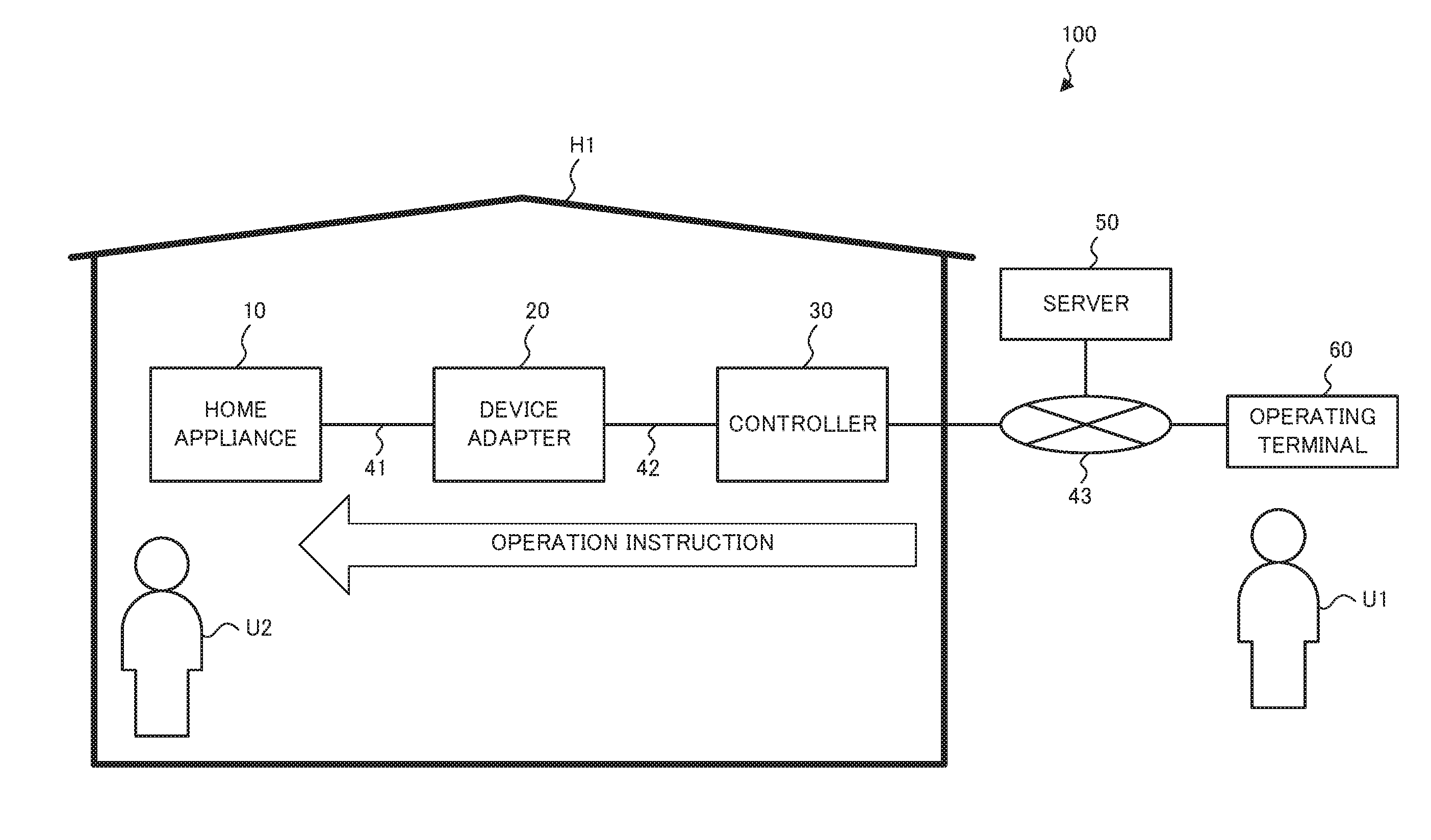
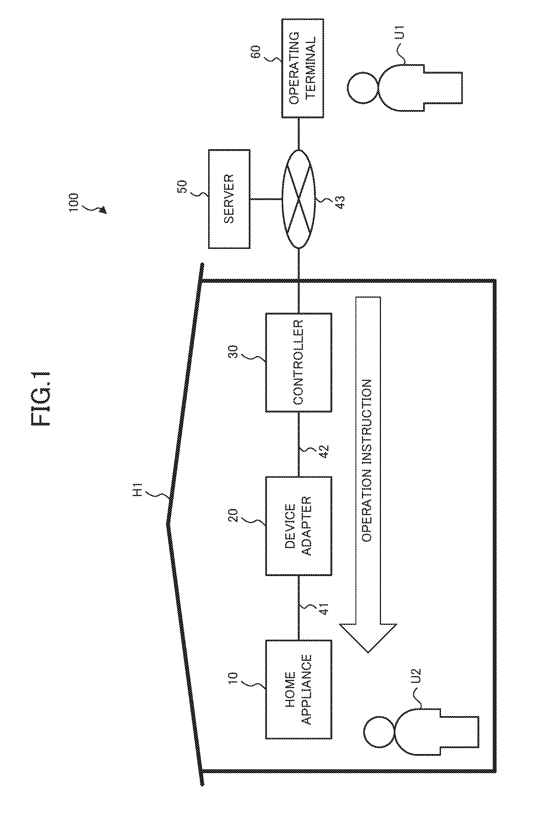
[0022]FIG. 1 illustrates a configuration of remote control system 100 according to Embodiment 1. The remote control system 100 is a system for remotely controlling a home appliance 10 via a network. The remote control system 100 includes, as illustrated in FIG. 1, the home appliance 10 installed in a home H1, a device adapter 20 for connecting the home appliance 10 to a controller 30, the controller 30 for controlling the home appliance 10, a server 50 connected to the Internet, and an operating terminal 60 for a user U1 to enter operation details.

[0023]The home appliance 10 and the device adapter 20 are communicatively connected to each other through a communication line 41. The communication line 41 is a cable, for example for serial communication. The communication line 41 is for transmitting operation instructions for control of the home appliance 10 from the device adapter 20 to the home appliance 10.

[0024]The device adapter 20 and the controller 30 are communicatively connecte...

embodiment 2

[0138]Subsequently, Embodiment 2 is described mainly with a focus on differences from Embodiment 1 as described above. Components that are identical or equivalent to Embodiment 1 as described above are given like numerals, and the descriptions thereof are omitted or simplified.

[0139]A remote control system 100 of Embodiment 2 is different from that of Embodiment 1 in that a controller 30 has a periodic transmission function. The periodic transmission function is a function of periodically transmitting periodic signals to a device adapter 20. The periodic signals are transmitted, for example at 10 second intervals. The periodic signals are used by the device adapter 20 to detect a communication interruption on the communication line 42.

[0140]FIG. 12 illustrates adapter processing according to the present embodiment. As illustrated in FIG. 12, when the determination in Step S205 is affirmative (Step S205; Yes), a communication establishing module 21a inquires of the controller 30 whet...


PUM


Abstract

A remote control system (100) includes a home appliance (10) and a relay device (20, 30) for relaying transmission of an operation instruction for controlling the home appliance (10). The home appliance (10) includes a first detector for detecting a communication interruption on a first communication line (41, 42) for transmission of the operation instruction from the relay device (20, 30) to the home appliance (10), a receiver for receiving, from the relay device, an interruption signal indicating a communication interruption on a second communication line (42, 43) for transmitting the operation instruction from a communication device to the relay device (20, 30), and a state changer for changing a state of the home appliance in accordance with a duration of at least one of the communication interruption detected by the first detector or the communication interruption indicated by the interruption signal. The relay device (20, 30) includes a second detector for detecting the communication interruption on the second communication line (42, 43), and a transmitter for transmitting the interruption signal to the home appliance (10) when the communication interruption is detected by the second detector.

Description

TECHNICAL FIELD[0001]The present disclosure relates to a remote control system, a home appliance, a relay device, an appliance management method, and a program.BACKGROUND ART[0002]Numerous appliances having a function of connecting to a home network have been commercially available in recent years. A user can, for example, operate such appliances via the network using this function. However, when the communication via the network is interrupted for some reason, the user loses the ability to operate the appliances via the network. To address this concern, techniques for detecting the communication interruption to recognize the inoperability of the appliances have been proposed (see, for example, Patent Literature 1).CITATION LISTPatent Literature[0003]Patent Literature 1: Unexamined Japanese Patent Application Kokai Publication No. 2005-184481SUMMARY OF INVENTIONTechnical Problem[0004]In a system disclosed in Patent Literature 1, the communication interruption during the operation of...

Claims


Application Information

Patent Timeline
IPC IPC(8): G05B15/02H04L12/28
CPCG06F13/00H04M11/00H04Q9/00G08C17/02H04L12/2816G08C2201/40H04L12/2818H04L12/283G05B15/02H04L12/2803
Inventor MINEZAWA, SATOSHIYANO, HIROTOSHIYABE, MASAAKIMARUYAMA, ICHIRO
Owner MITSUBISHI ELECTRIC CORP
Learn More