
Transmission of measurement reports in a wireless communication system

a wireless communication system and measurement report technology, applied in the field of telecommunications equipment and methods, can solve the problems of requiring more complex and expensive radio transceivers and decoders to implement, and achieve the effect of reducing the overhead of uplink signalling, reducing the overall data transfer rate of the system, and reducing the cost of implementation

Active Publication Date: 2016-07-28
SONY CORP
View PDF10 Cites 8 Cited by
  • Summary
  • Abstract
  • Description
  • Claims
  • Application Information

AI Technical Summary

Benefits of technology

The patent describes a technique for optimizing data transfer rates in a communication system by using CQI reports received from terminal devices. These reports provide information about the quality of the channel conditions, which helps the base station allocate transmission resources effectively. However, high-resolution CQI reporting requires more uplink signalling from the terminal device, which may cause difficulties in the system. The inventors have realized that this balance between high resolution and uplink signaling overhead may be different for virtual carrier operation and non-virtual carrier operation. The technical effect of this patent is to improve the efficiency of data transfer in a communication system by optimizing resource allocation based on CQI reports while balancing the need for high-resolution reporting with the associated uplink signaling overhead.

Problems solved by technology

However, third and fourth generation mobile telecommunication networks typically employ advanced data modulation techniques and support wide bandwidth usage on the radio interface which can require more complex and expensive radio transceivers and decoders to implement.
However, with high-resolution CQI reporting comes an increased uplink signalling overhead from the terminal device.

Method used


Image

  • Transmission of measurement reports in a wireless communication system
  • Transmission of measurement reports in a wireless communication system
  • Transmission of measurement reports in a wireless communication system

Examples


Embodiment Construction

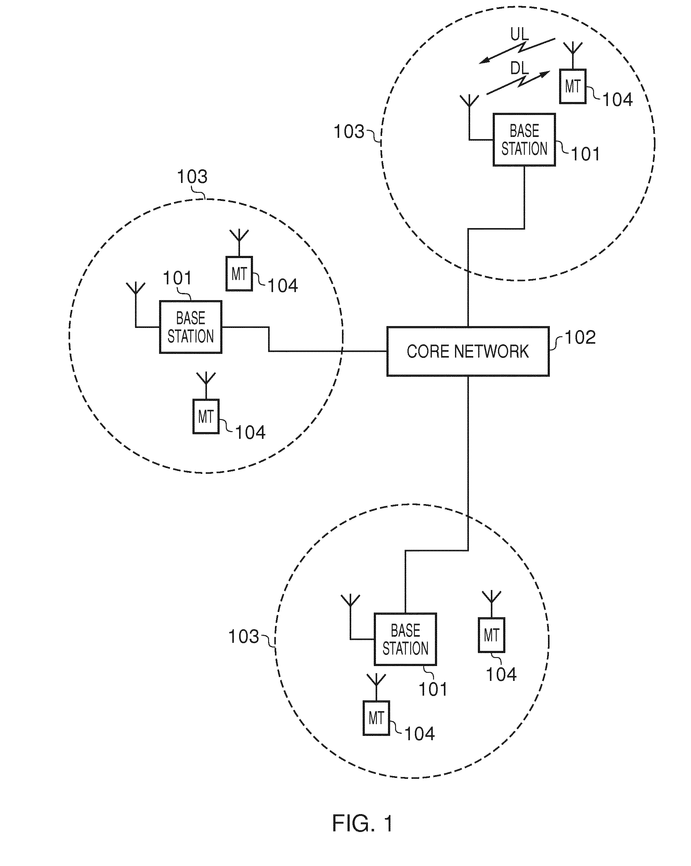
[0028]FIG. 1 provides a schematic diagram illustrating some basic functionality of a wireless telecommunications network / system 100 operating in accordance with LTE principles. Various elements of FIG. 1 and their respective modes of operation are well-known and defined in the relevant standards administered by the 3GPP (RTM) body and also described in many books on the subject, for example, Holma, H. and Toskala, A. [12].

[0029]The network 100 includes a plurality of base stations 101 connected to a core network 102. Each base station provides a coverage area 103 (i.e. a cell) within which data can be communicated to and from terminal devices 104. Data are transmitted from base stations 101 to terminal devices 104 within their respective coverage areas 103 via a radio downlink. Data are transmitted from terminal devices 104 to the base stations 101 via a radio uplink. The core network 102 routes data to and from the terminal devices 104 via the respective base stations 101 and provi...


PUM


Abstract

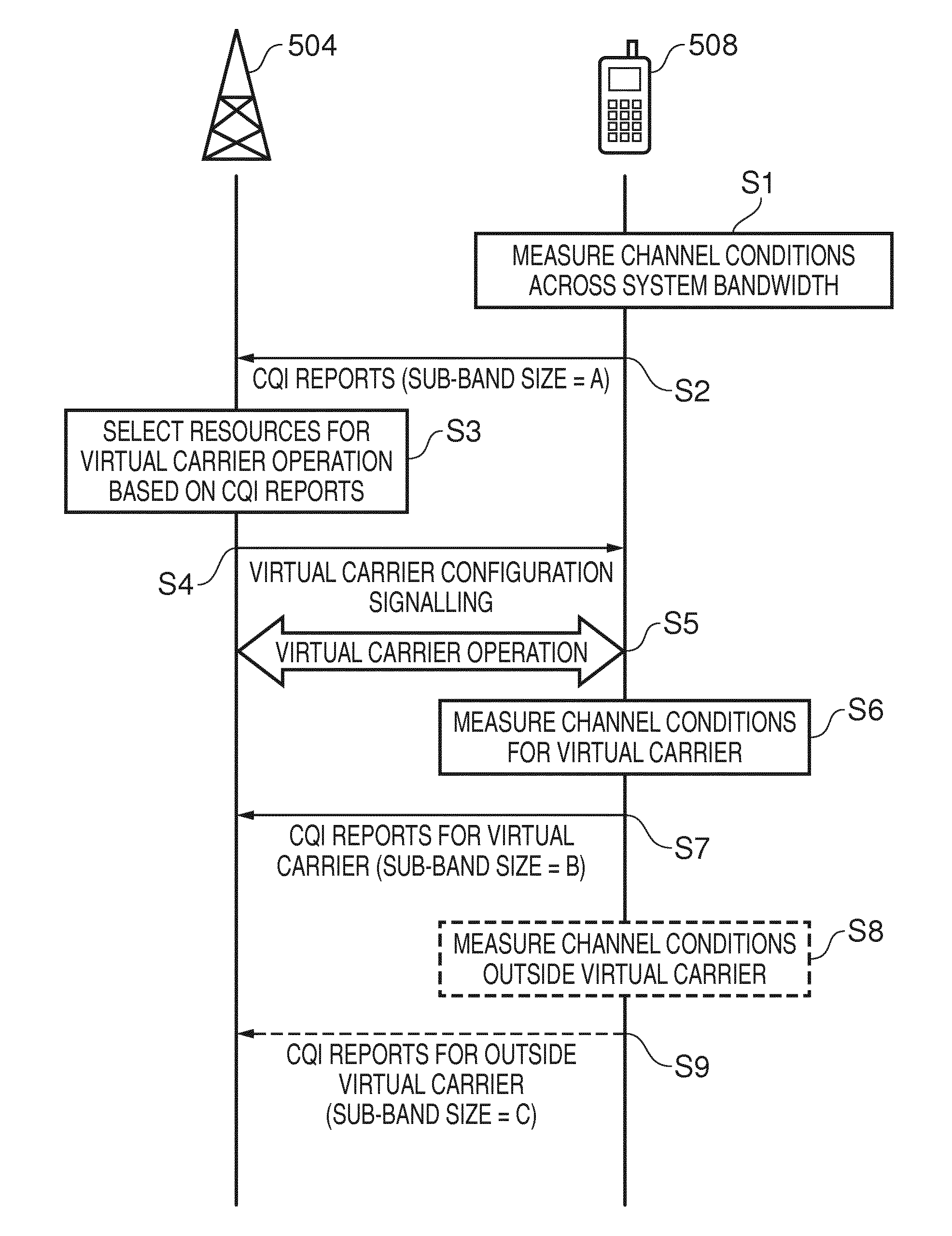
A wireless telecommunications system including a base station and terminal device, supporting a virtual carrier mode with downlink communications made by the base station using a radio interface spanning a system frequency bandwidth while the terminal device can receive at least some communications from the base station within a restricted subset of transmission resources selected from within the system frequency bandwidth providing a restricted bandwidth downlink. The terminal device can measure channel conditions across the system frequency bandwidth and transmit corresponding measurement reports to the base station. Measurement reports for transmission resources not including the restricted bandwidth downlink channel may be aperiodic while measurement reports for transmission resources including the restricted bandwidth downlink channel may be periodic. Measurement reports for transmission resources not including the restricted bandwidth downlink channel may be based on a subset of the channel condition measurements selected because they are associated with relatively poor channel conditions.

Description

BACKGROUND[0001]1. Field[0002]The present disclosure relates to telecommunications apparatus and methods.[0003]2. Description of Related Art[0004]The “background” description provided herein is for the purpose of generally presenting the context of the disclosure. Work of the presently named inventors, to the extent it is described in this background section, as well as aspects of the description which may not otherwise qualify as prior art at the time of filing, are neither expressly or impliedly admitted as prior art against the present invention.[0005]The present disclosure relates to wireless telecommunications systems and methods, and in particular to systems and methods for restricted frequency resource / virtual carrier operation in wireless telecommunication systems.[0006]Mobile communication systems have evolved over the past ten years or so from the GSM System (Global System for Mobile communications) to the 3G system and now include packet data communications as well as cir...

Claims


Application Information

Patent Timeline
Patent Type & Authority Applications(United States)
IPC IPC(8): H04W24/08H04W72/08H04W24/10
CPCH04W24/08H04W72/085H04W24/10H04L5/0053H04L1/0026H04W72/542
Inventor WAKABAYASHI, HIDEJIWEBB, MATTHEW WILLIAM
Owner SONY CORP
Learn More