
Video switch and switching method thereof

a video switch and switching method technology, applied in the field of video switches, can solve the problems of long delay and undesirable visual effect for viewers, and achieve the effects of preventing the problem of blank screen during the switching, reducing the number of times of image out, and reducing the cos

Active Publication Date: 2016-07-28
ATEN INT CO
View PDF0 Cites 7 Cited by
  • Summary
  • Abstract
  • Description
  • Claims
  • Application Information

AI Technical Summary

Benefits of technology

The video switch described in this patent uses simple hardware and asynchronous switching of I2C and TMDS to create a faster and more affordable way to switch between images. This technology also prevents the issue of blank screens during switches.

Problems solved by technology

These cause long delays and undesirable visual effect for the viewer.

Method used


Image

  • Video switch and switching method thereof
  • Video switch and switching method thereof
  • Video switch and switching method thereof

Examples


Embodiment Construction

[0016]Embodiments of the present invention are described below with reference to the drawings. While the embodiments are described in specific details, it should be understood that these specific details do not limit the scope of the present invention. Also, to avoid overcrowding in the drawings, some commonly known structural elements are shown schematically in the drawings.

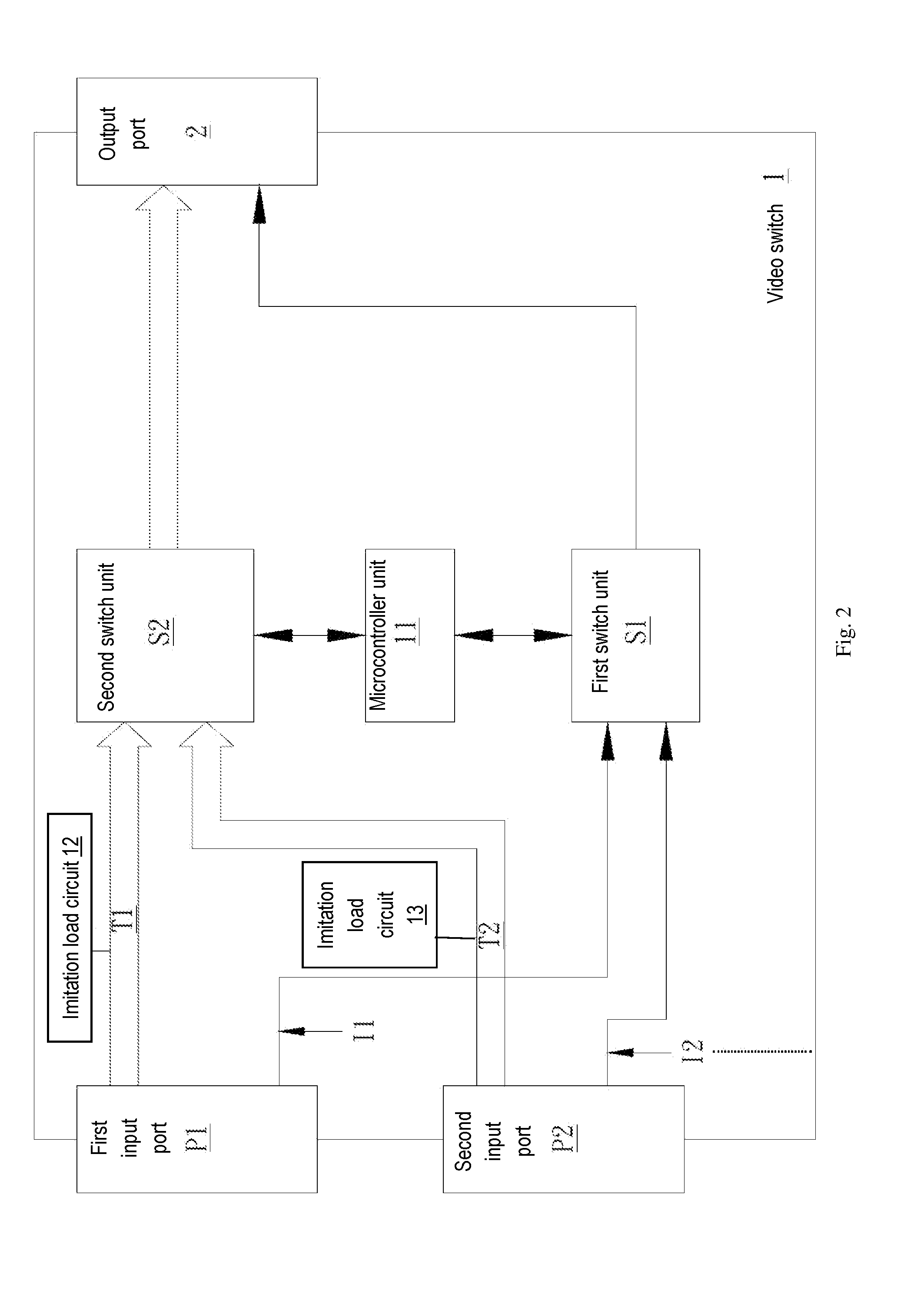
[0017]Refer to FIG. 2 and FIG. 3. FIG. 2 is a schematic block diagram of a video switch according to an embodiment of the present invention, and FIG. 3 schematically illustrates an input port switching scheme according to an embodiment of the present invention. The video switch 1 has a first input port P1, a second input port P2, a first switch unit S1, a second switch unit S2, a microcontroller unit 11, and an output port 2. The first input port P1 includes a first Transition Minimized Differential Signaling (TMDS) transmission channel T1 for transmitting a first TMDS signal TMDS(1) and a first Inter-Integrated...


PUM


Abstract

The present invention provides a video switch and a switching method thereof. The video switch comprises a first input port configured to transmit a first Transition Minimized Differential Signaling (TMDS) and a first Inter-Integrated Circuit (I2C) signal; a second input port configured to transmit a second Transition Minimized Differential Signaling (TMDS) and a second Inter-Integrated Circuit (I2C) signal; a first switch unit and a second switch unit. When switching the first input port to the second input port, the video switch firstly outputs the second Inter-Integrated Circuit (I2C) signal a specific time and then outputs the second Transition Minimized Differential Signaling (TMDS).

Description

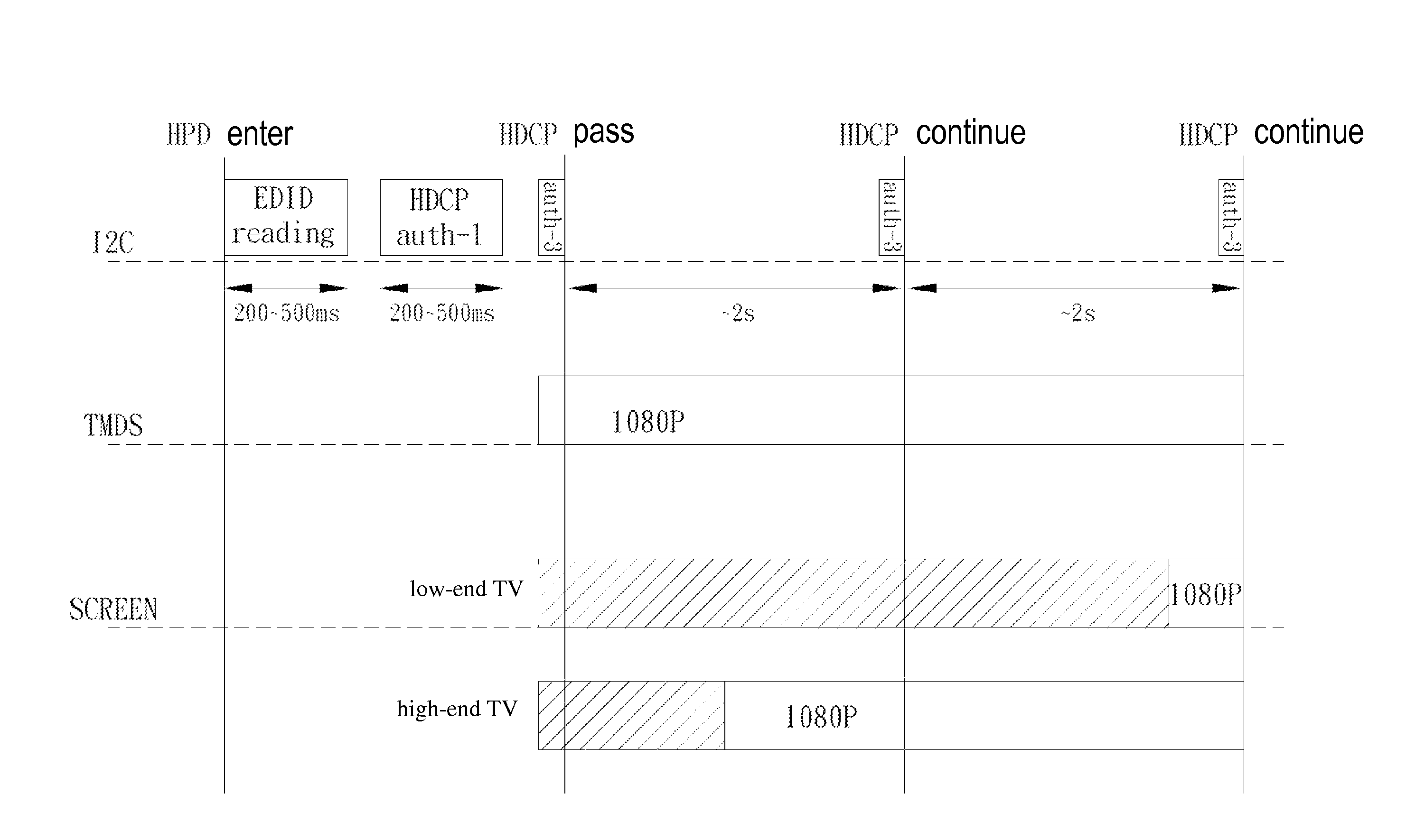
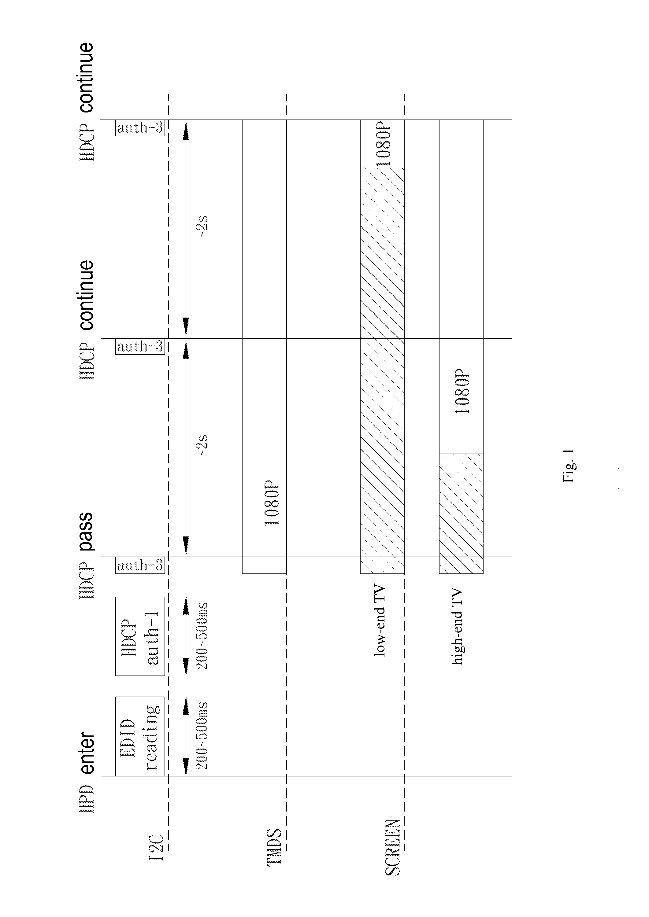
BACKGROUND OF THE INVENTION[0001]1. Field of the Invention[0002]This invention relates to a video switch and related switching method, and in particular, it relates to an asynchronous video switch and related switching method.[0003]2. Description of Related Art[0004]In recent years, HDMI interface, which is a digital transmission interface more efficient and faster than the DVI interface, has been developed. More and more digital audio and video equipment (such as playback device, display device, etc.) are now adopting this interface. Also, a High-Bandwidth Digital Content Protection (HDCP) standard is developed in recent years to protect copyright of digital audio and video content and prevent illegal duplication or spreading of such content during transmission or playing. The HDCP standard includes an authentication protocol; using such a protocol, the HDCP transmitting device (such as a playback device) can confirm whether a particular HDCP receiving device (e.g. a display device...

Claims


Application Information

Patent Timeline
Patent Type & Authority Applications(United States)
IPC IPC(8): H04N5/268
CPCH04N5/268H04N21/43635G09G5/006G09G2370/047G09G2370/12G09G2370/20G09G2370/22G09G5/00
Inventor KUO, HUEI-JEN
Owner ATEN INT CO
Learn More