
Test structure to measure delay variability mismatch of digital logic paths

Active Publication Date: 2016-07-21
IBM CORP
View PDF0 Cites 2 Cited by
  • Summary
  • Abstract
  • Description
  • Claims
  • Application Information

AI Technical Summary

Benefits of technology

The invention provides technical benefits such as faster measurement time, improved accuracy, compact structure, and efficient data collection. It allows for a single analog voltage measurement that represents the fraction of logic delay paths that have a delay less than a certain threshold delay. Additionally, it uses paths built with a small number of stages, as opposed to traditional methods that use many stages and are more immune to local variability. Overall, this invention provides faster, more efficient, and accurate results for measuring the performance of semiconductor devices.

Problems solved by technology

RO-based approaches generally employ too many stages to accurately represent realistic path lengths in actual circuits.
Furthermore, RO-based approaches do not account for clock skew and / or jitter at the latches at the beginning and / or end of the delay path (because there are no latches in ROs), and RO-based approaches do not generally represent actual logic gates with correct fan-outs, threshold voltages, combination(s) of logic gates, and the like.

Method used


Image

  • Test structure to measure delay variability mismatch of digital logic paths
  • Test structure to measure delay variability mismatch of digital logic paths
  • Test structure to measure delay variability mismatch of digital logic paths

Examples


Embodiment Construction

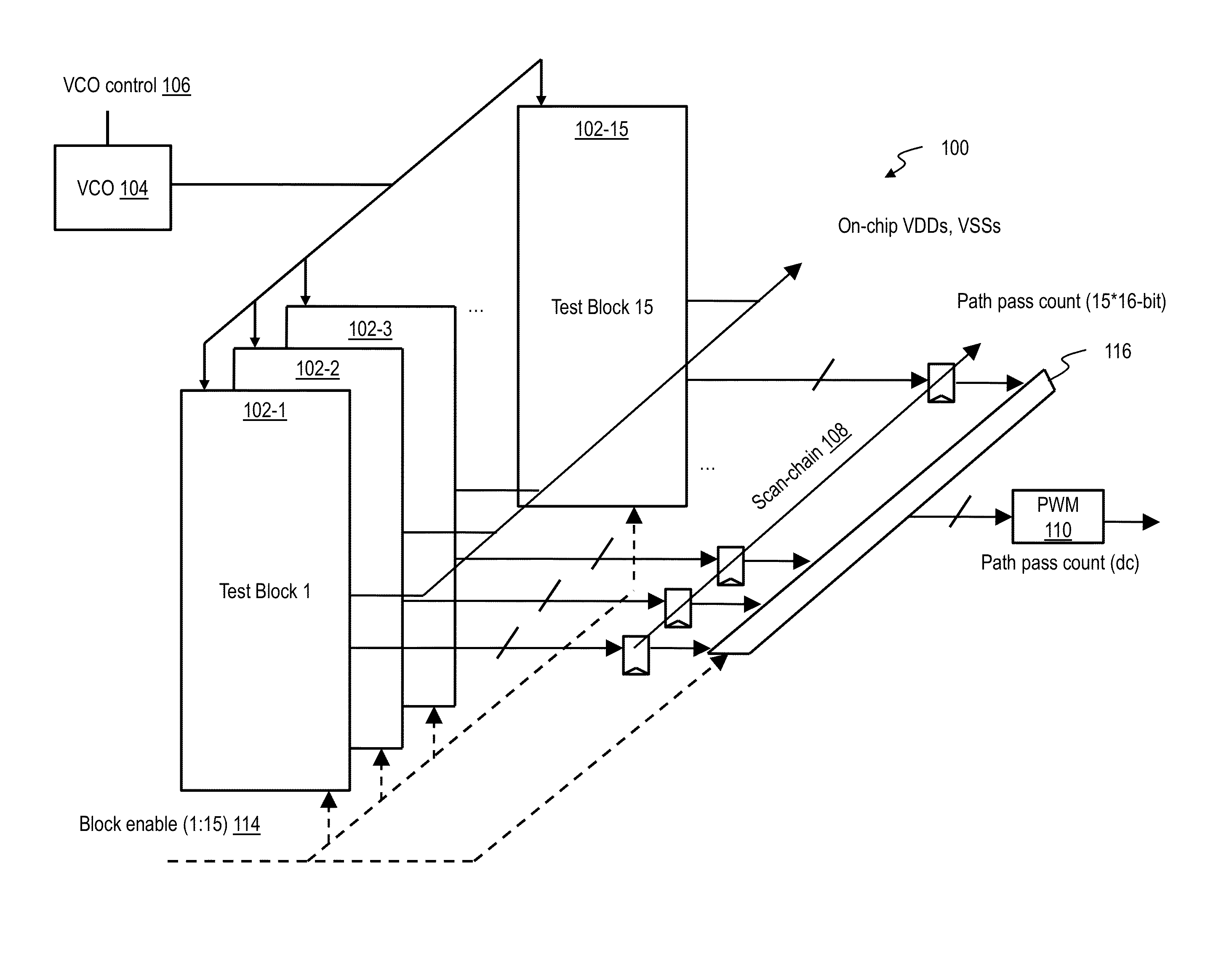
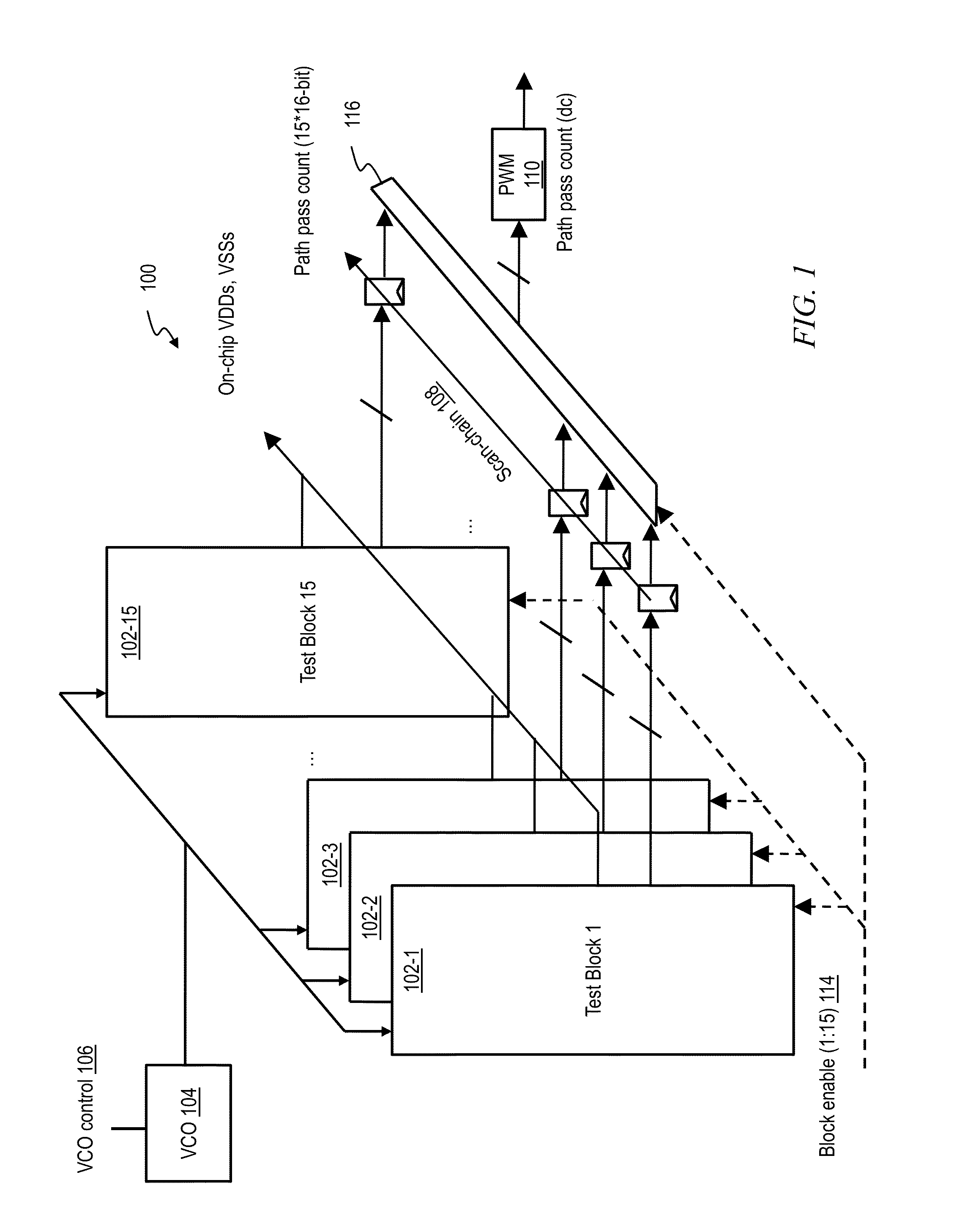
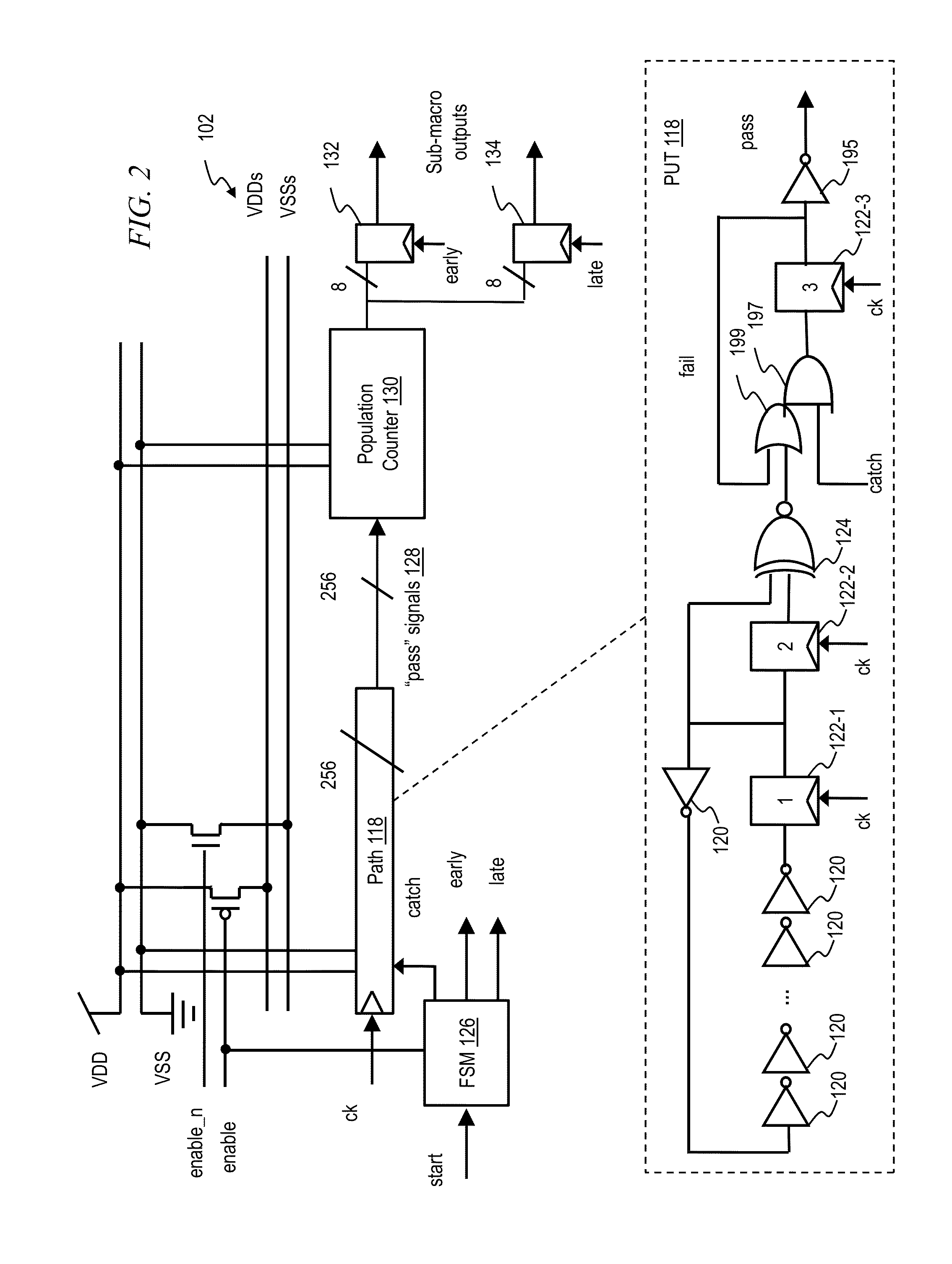
[0023]As noted, it is desirable to be able to measure mismatch in digital logic path delay variations. Current techniques employ ring oscillators (RO). RO-based approaches generally employ too many stages to accurately represent realistic path lengths in actual circuits. If the RO does have the correct number of stages, it does not have the correct slew rates. Furthermore, RO-based approaches do not account for clock skew and / or jitter at the latches at the beginning and / or end of the delay path (because there are no latches in ROs), and RO-based approaches do not generally represent actual logic gates with correct fan-outs, threshold voltages, combination(s) of logic gates, and the like. In addition, ROs are run one at a time, and measured one at a time. In contrast, in one or more embodiments, all instantiations of the paths run in parallel and hence measurement time is significantly improved. Furthermore, ROs require a high-speed output pad for frequency measurement, whereas one ...


PUM


Abstract

An integrated circuit includes a test block which in turn includes a plurality of identical paths; a counter selectively coupled to the plurality of identical paths to selectively obtain a count of at least one of correctly operating paths and incorrectly operating paths from each of the plurality of identical paths; and a plurality of count latches selectively coupled to the counter to store output of the counter. Each path in turn includes a first clocked latch; a clocked logic path beginning and ending at the first clocked latch; and a clocked detection circuit coupled to the first clocked latch and the counter, which determines whether the clocked logic path is operating properly in a given clock period.

Description

CROSS-REFERENCE TO RELATED APPLICATIONS[0001]This patent application claims the benefit of U.S. Provisional Patent Application 62 / 105,902 filed Jan. 21, 2015, the complete disclosure of which, including appendices, is hereby expressly incorporated herein by reference in its entirety for all purposes.FIELD OF THE INVENTION[0002]The present invention relates to the electrical, electronic and computer arts, and, more particularly, to design and test of electronic circuits to take into account process variability, and the like.BACKGROUND OF THE INVENTION[0003]It is desirable to be able to measure mismatch in digital logic path delay variations. Current techniques employ ring oscillators (RO). RO-based approaches generally employ too many stages to accurately represent realistic path lengths in actual circuits. If the RO does have the correct number of stages, it does not have the correct slew rates. Furthermore, RO-based approaches do not account for clock skew and / or jitter at the latc...

Claims


Application Information

Patent Timeline
IPC IPC(8): G01R31/3177G01R31/28
CPCG01R31/2884G01R31/3177G01R31/31726
Inventor BALAKRISHNAN, KARTHIKFLEISCHER, BRUCE M.JENKINS, KEITH A.VEZYRTZIS, CHRISTOS
Owner IBM CORP
Learn More