
Adaptive Error Correction Code for Optical Super-Channels

a super-channel and error correction technology, applied in the field of coherent optical communication systems, can solve the problems of increasing serial adc sampling rate, changing the nonlinearity-induced distortion of other channels, and difficult to implement single-wavelength coherent detection at data rates greater than 100 gbit/s, so as to achieve the effect of improving performance over optical channels

Active Publication Date: 2016-07-14
MITSUBISHI ELECTRIC RES LAB INC
View PDF1 Cites 15 Cited by
  • Summary
  • Abstract
  • Description
  • Claims
  • Application Information

AI Technical Summary

Benefits of technology

The patent is about improving the performance of optical communication channels that have non-flat noise and distortion power spectrum. This is done by transmitting a super-channel over several non-adjacent wavelengths in a point-to-point link. The technical effect is better performance of optical communication channels.

Problems solved by technology

However, an increase in serial ADC sampling rates is difficult to implement for single-wavelength coherent detection at data rates greater than 100 Gbit / s.
However, the small size of the gap between frequencies of different sub-channels cause nonlinearity of noise in the sub-channels, i.e., each sub-channel receives different nonlinearity-induced phase noise causing non uniformity in the bit-error-ratio (BER) across the sub-channels.
However, the increase of the transmission power for one channel also changes the nonlinearity-induced distortion of other channels.
Therefore, it is difficult to adjust the power levels of all the sub-channels in the same fiber to meet the BER requirements.

Method used


Image

  • Adaptive Error Correction Code for Optical Super-Channels
  • Adaptive Error Correction Code for Optical Super-Channels
  • Adaptive Error Correction Code for Optical Super-Channels

Examples


Embodiment Construction

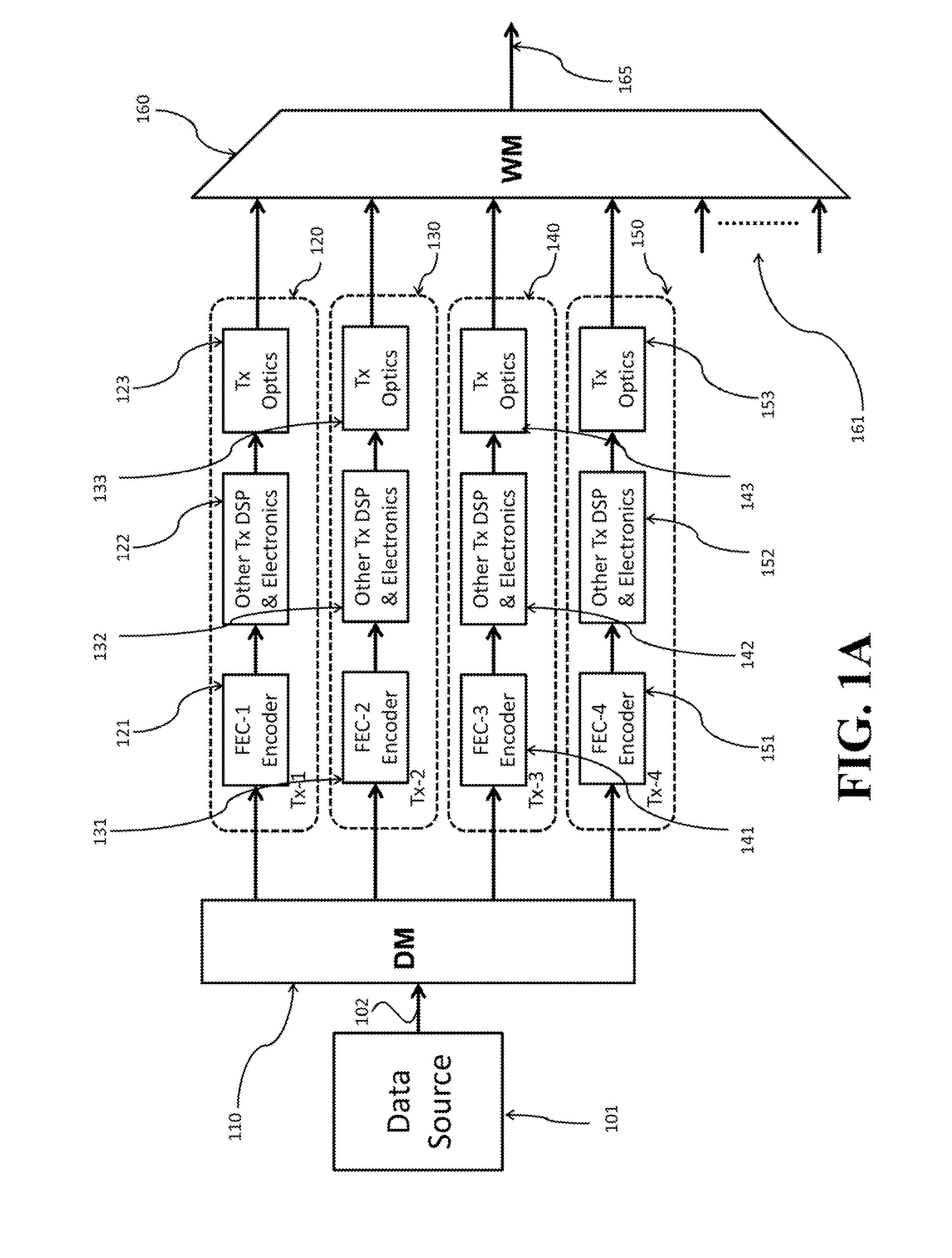
[0021]FIG. 1A shows a block diagram of a super-channel transmitter for transmitting data to a receiver over an optical super-channel formed by a set of sub-channels of different wavelengths. FIG. 1B shows a flow chart of a method for transmitting the data that can be implemented by the super-channel transmitter of FIG. 1A.

[0022]Some embodiments of the invention are based on a realization that the data transmitted over the super-channel can be partitioned unequally into a set of data streams for transmission over the sub-channels. Usually, the bit rate and the size of the data transmitted over the entire super-channel are fixed. However, according to the embodiments, only the bit rates are fixed for the sub-channels, and the size of the transmitted data streams can vary for different sub-channels as long as the sum of the data transmitted over all sub-channels equals the fixed data transmitted over the super-channel.

[0023]According to various embodiments of the invention, the super-c...


PUM


Abstract

A method for transmitting data over an optical super-channel partitions the data unequally into a set of data streams for transmission over the set of sub-channels of the super-channel, such that a size of a first data stream for transmission over a first sub-channel is different than a size of a second data stream of the data for transmission over a second sub-channel. The method encodes each data stream of the data with an error correction code (ECC) having different ECC rates to produce a set of encoded data streams and transmits concurrently the set of encoded data streams over the set of sub-channels of the super-channel. Accordingly, the method uses an adaptive ECC for optical super-channels, such that a first ECC rate for encoding the first data stream is different than a second ECC rate for encoding the second data stream.

Description

FIELD OF THE INVENTION[0001]This invention relates generally to coherent optical communications systems, and more particularly to transmitting data over an optical super-channel.BACKGROUND OF THE INVENTION[0002]Coherent optical communications enable data to be transmitted over long haul (typically >2,000 kin) optical transmission networks at higher data rates. A coherent detector requires that the received phase modulated optical signal is digitized for a digital signal processor (DSP). Digitizing the received signal requires a high speed analog-to-digital converter (ADC). However, an increase in serial ADC sampling rates is difficult to implement for single-wavelength coherent detection at data rates greater than 100 Gbit / s.[0003]A super-channel is an evolution in dense wavelength division multiplexing (DWDM) in which multiple coherent optical carriers are combined on a single super-channel at a higher data rate, and is brought into service in a single operational cycle. Rather ...

Claims


Application Information

Patent Timeline
Patent Type & Authority Applications(United States)
IPC IPC(8): H04L1/00H04J14/02H04B10/079
CPCH04L1/0041H04L1/0045H04J14/02H04B10/07953H04L1/0009H04J14/0307H04J14/0298H04J14/0257H04J2203/0076
Inventor KOJIMA, KEISUKEPARSONS, KIERANMILLAR, DAVIDKOIKE-AKINO, TOSHIAKI
Owner MITSUBISHI ELECTRIC RES LAB INC
Learn More