Device for a current limiter and a current limiter comprising said device
a current limiter and current limiter technology, applied in the direction of superconducting magnets/coils, magnetic bodies, electrical devices, etc., can solve the problems of limiting the material choices open to circuit designers, complicated manufacturing process, and use of different materials, so as to achieve rapid and even transition of superconducting elements
- Summary
- Abstract
- Description
- Claims
- Application Information
AI Technical Summary
Benefits of technology
Problems solved by technology
Method used
Image
Examples
first embodiment
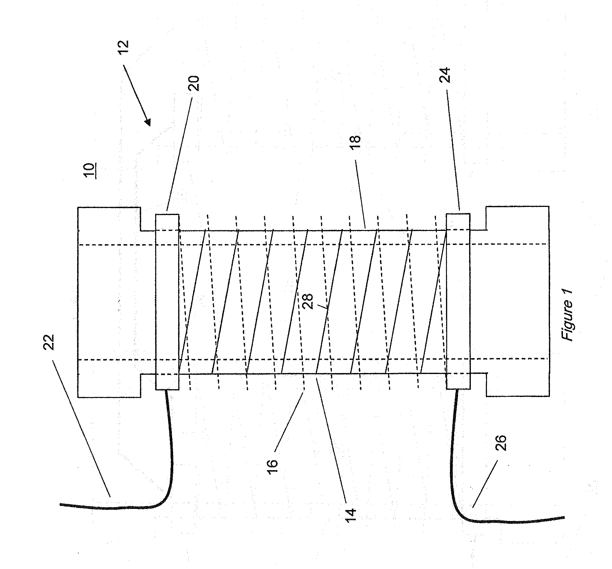
[0033]With reference to FIG. 1, a device 10 according to a first embodiment of the invention comprises coil assembly 12 adapted to carry a current. The coil assembly 12 comprises two coils 14, 16, each comprising a superconducting element, connected in parallel such that each coil 14, 16 carries a portion of the current through the coil assembly 12. The two coils 14, 16 are arranged such that, when the superconducting elements of the coils 14, 16 are each in a superconducting state with a current flowing through the coil assembly 12, the magnetic fields generated by the two coils 14, 16 substantially cancel each other. In this embodiment, this is achieved by arranging the coils 14, 16 as two concentric, preferably coaxial helical coils 14, 16, having a similar diameter and length, connected in parallel and wound in opposition so that the currents in the two coils 14, 16, flow around the axis of the coils in opposite rotational senses. This reduces the magnetic flux density in the re...
second embodiment
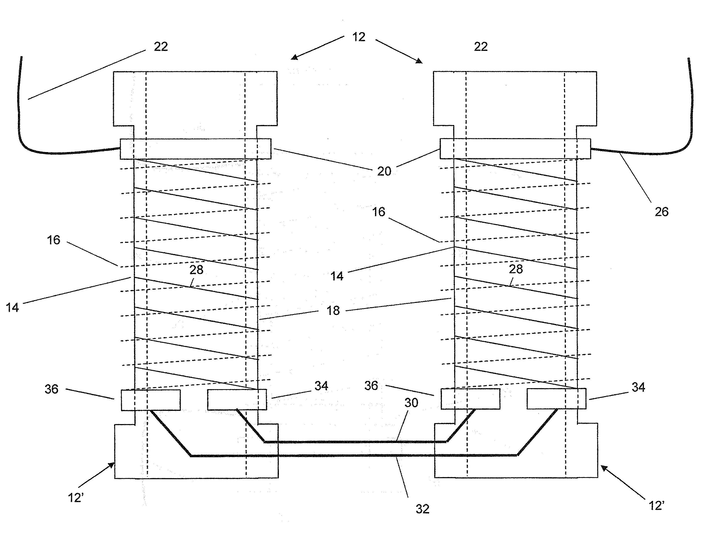
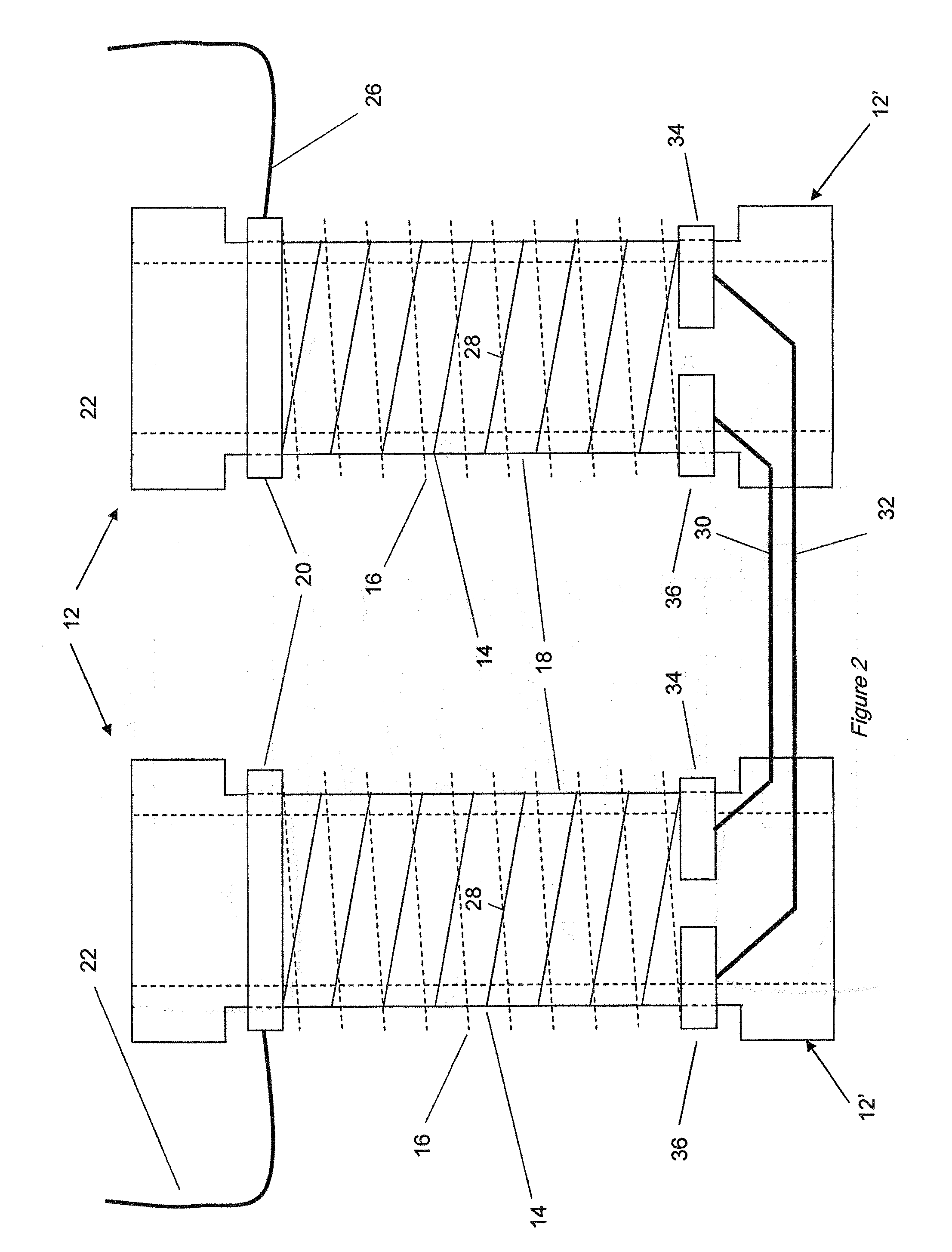
[0043]With reference to FIG. 2, a device 10′ according to a second embodiment of the invention comprises multiple coil assemblies 12′, connected in series, for example to allow the operation of the device 10′ at higher voltage levels. Components which have been described in connection with the first embodiment above are indicated by the same reference numerals. Where it is necessary to connect multiple coil assemblies 12′ in series, the conducting paths through the first and second coils 14, 16 are kept separate throughout the series connected assemblies 12′, by means of connecting all of the first (higher current or lower Ic) coils 14 in series, connecting all of the second (lower current or higher Ic) coils 16 in series and making the parallel connection of the two sets of series connected coils 14, 16 only at the extremities of said sets. This arrangement, applied to two series connected coil assemblies 12′ is shown schematically in FIG. 2. The connections 30, 32 between the coil...
third embodiment
[0044]FIG. 3 shows a further embodiment of a coil assembly 12″ for connection in between the coil assemblies 12′ of the second embodiment where more than two are required to be connected in series. Components which have been described in connection with the first or second embodiments above are indicated by the same reference numerals. A pair of first end electrodes 38, 40 and a pair of second end electrodes 34, 36 allow independent connection to subsequent coil assemblies 12″, 12′ at both ends of the coil assembly 12″. To simplify manufacture, it may be desirable to construct all coil assemblies in this way and to link the end electrodes (e.g. to link end electrodes 34 and 36, or to link end electrodes 38, 40) at the extremities of the two sets of series connected coils, at the point where the external connections 22, 26 are provided.
[0045]Those skilled in the art will appreciate that this method of interconnection is provided to ensure that under any fault conditions including fau...
PUM
 Abstract
Description
Claims
Application Information
 - R&D
- Intellectual Property
- Life Sciences
- Materials
- Tech Scout
- Unparalleled Data Quality
- Higher Quality Content
- 60% Fewer Hallucinations
Browse by: Latest US Patents, China's latest patents, Technical Efficacy Thesaurus, Application Domain, Technology Topic, Popular Technical Reports.
© 2025 PatSnap. All rights reserved.Legal|Privacy policy|Modern Slavery Act Transparency Statement|Sitemap|About US| Contact US: help@patsnap.com


