
Electrochromic media for producing a preselected color and devices comprising same

a technology of electrochromic media and preselected color, which is applied in the direction of organic chemistry, instruments, chemistry apparatus and processes, etc., can solve the problems of inability to acceptably produce gray shades, change of light reflectance of mirrors, and limited colors obtainable to date, so as to achieve the effect of contributing to the spectrum of mediums and higher relative proportions

Inactive Publication Date: 2001-09-11
GENTEX CORP
View PDF21 Cites 36 Cited by
  • Summary
  • Abstract
  • Description
  • Claims
  • Application Information

AI Technical Summary

Benefits of technology

The net effect is that a much higher relative proportion of electroactive compounds with low redox potential are elevated to the oxidized state. For example, in a medium with only one anodic electrochromic compound, only 30% of the electrochromic compound molecules may be oxidized at any given time. In a medium with two anodic electroactive compounds of differing redox potential, of the total of the oxidized anodic species [A.sub.H.sup.+ ] and [A.sub.L.sup.+ ], perhaps 80% will be [A.sub.L.sup.+ ] species derived from the electrochromic compound of lower redox potential. Thus, electroactive components with a more easily accessible electrochemically activated state will make a more significant contribution to the absorbance spectrum of the medium than one would attribute based solely on their abundance in the medium. This enhanced contribution to the spectrum of the medium is a direct result of the fact that its electrochemically activated state is more easily accessible and is present in higher relative proportions than the mole ratio of the unactivated form to the total material of its redox type in the medium. This mole ratio is less than 28 mol percent, preferably below 25 mol percent, and most preferably below 20 mol percent.
While the above discussion has centered on anodic electroactive compounds, the same applies to cathodic electroactive compounds as well. Species derived from the more easily reduced electroactive compound will dominate the absorbance spectrum to a greater extent than can be attributed relative to its concentration. The more easily redoxible electroactive compounds can be selected for their color contribution and stability rather than cost, since they are used in minor amount.
The redox potentials give an indication of the ease of accessibility of the electrochemically activated state, thus the first compound in the table with a listed redox potential of -0.100V has a more easily accessible electrochemically activated state than the last entry of the table with a listed potential of -0.492V.
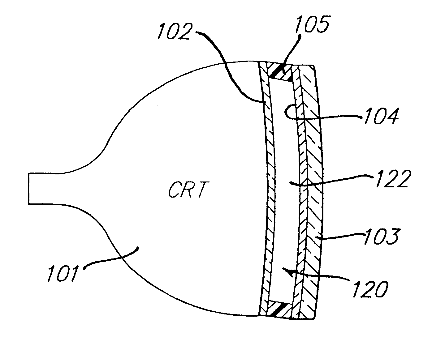
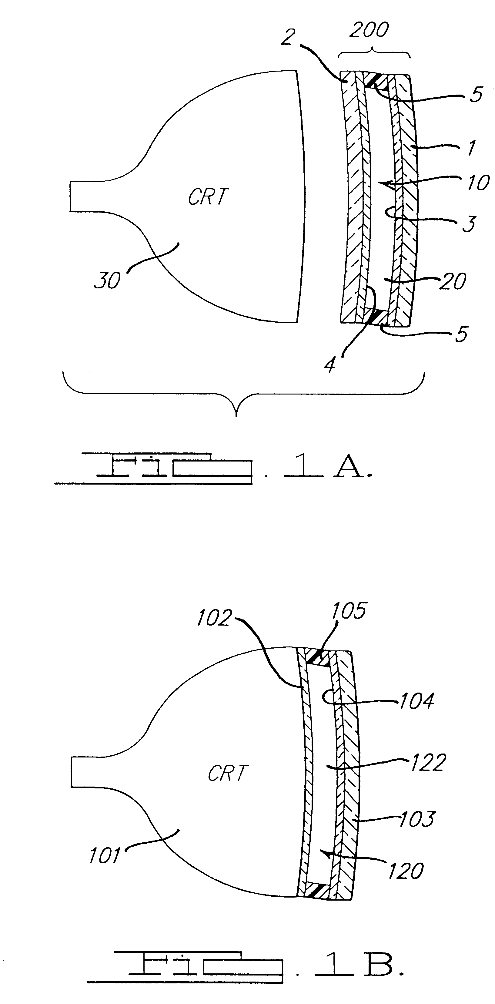
FIG. 1A shows a cross-sectional view of an electrochromic light filter associated with a CRT display. The electrochromic filter 200 includes two transparent elements 1 and 2 each with a transparent conductive coating 3,4 on the inward surface, and a seal or gasket 5 around the perimeter of the device which defines a cavity 10 into which the electrochromic medium 20 is confined. The device then can be laminated or otherwise attached to the viewing surface of a CRT display 30 to reduce the amount of glare due to ambient light.
The readability of a display such as a CRT or LCD device can be compromised by high ambient lights levels due to diffuse reflectance of the incident ambient light by the highly scattering inner surface of the display screen. The use of dark glass in the display screen (transmission level typically 30 to 70%) improves the contrast between emitted and reflected light, at the cost of higher power consumption and decreased resolution. A variable transmittance light filter, on the other hand, allows the CRT to be operated with low power in low ambient lighting conditions and with high power in high ambient lighting conditions, thereby decreasing power usage and increasing resolution of the CRT. A variable transmittance light filter further enhances the contrast between emitted and reflected light by decreasing the transmission level below 30%, and if necessary, to 20% or even 10%.

Problems solved by technology

Application of voltage across the inner conductive coatings results in a change of the light reflectance of the mirror.
The colors heretofore obtainable were limited both by the stability of available electrochromic compounds as well as economic factors such as their commercial availability and expense.
Prior art electrochromic media generally employed two electrochrornic compounds, one anodic and one cathodic, and were unable to acceptably produce gray shades, and numerous other shades of color as well.
This required close matching of redox potentials limits the choices available for electrochromic compounds.
Thus, many electrochromic compounds which are relatively less expensive or which exhibit greater stability cannot be used when certain target colors and / or devices are envisioned because their redox potentials are unsuitable and prevent their being used in an electrochromic device.

Method used


Image

  • Electrochromic media for producing a preselected color and devices comprising same
  • Electrochromic media for producing a preselected color and devices comprising same
  • Electrochromic media for producing a preselected color and devices comprising same

Examples


example 1

20 mM 5,10-dimethyl-5,10-dihydrophenazine, 8 mM 2,3-diphenyl-5,10-diethyl-5,10-dihydrophenazine (28.6 mol percent), 34 mM 1,1'-bisphenyl-4,4'-dipyridinium bis(tetra-fluoroborate).

Application of 1.2V across each of the electrochromic devices results in uniform coloration. The device containing electrochromic medium C1 changes from light yellow to bright green, while the device containing electrochromic medium 1 changes from light tan to dull grayish-green. There is no staging noticed during darkening or clearing.

example 2

20 mM 2-vinyl-5,10-dimethyl-5,10-dihydrophenazine, 8 mM 2,3-diphenyl-5,10-diethyl-5,10-dihydrophenazine (28.6 mol percent), 34 mM 1,1'-ethylene-4,4'-dimethyl-2,2'-dipyridinium bis(hexafluorophosphate)

Application of 1.2V across each of the electrochromic devices results in uniform coloration. The device containing electrochromic medium C2 changes from light yellow to dull yellow-tan, while the device containing electrochromic medium 2 changes from light yellow to rust-orange. There is no staging noticed during darkening or clearing.

example 3

An electrochromic medium containing a electrochromic compound composition consisting of 22 mM 5,10-dimethyl-5,10-dlihydrophenazine, 6 mM 1 2-methyl-3-phenyl-5,10-dimethyl-5,10-dihydrophenazine (21 mol percent), and 34 mM 1,1'-bis(phenylpropyl)-4,4'-dipyridinium bis(tetrafluoroborate) in propylene carbonate is deoxygenated with dry nitrogen.

Application of 1.2V across the electrochromic device containing the electrochromic medium of Example 3 results in uniform coloration. The device changes from colorless to blue-gray. There is no staging noticed during darkening or clearing.


PUM

PropertyMeasurementUnit
electrically conductiveaaaaaaaaaa
electrochromicaaaaaaaaaa
cathodic electrochromicaaaaaaaaaa

Abstract

Electrochromic compositions suitable for use in electrochromic media in electrochromic devices contain minimally two electrochromic compounds of the same redox type, whose redox potentials are greater than 30 mV. The lower redox potential electrochromic compound makes a large contribution to the absorbancy of the electrochromic medium despite being present in only minor concentration.

Description

The present invention is directed to electrochromic devices. More particularly, the present invention pertains to improved electrochromic media capable of producing a preselected color.Electrochromic devices, and electrochromic media suitable for use therein, are the subject of numerous U.S. patents, including U.S. Pat. No. 4,902,108, entitled "Single-Compartment, Self-Erasing, Solution-Phase Electrochromic Devices, Solutions for Use Therein, and.Uses Thereof", issued Feb. 20, 1990 to H. J. Byker; Canadian Pat. No. 1,300,945, entitled "Automatic Rearview Mirror System for Automotive Vehicles", issued May 19, 1992 to J. H. Bechtel et al.; U.S. Pat. No. 5,128,799, entitled "Variable Reflectance Motor Vehicle Mirror", issued Jul. 7, 1992 to H. J. Byker; U.S. Pat. No. 5,202,787, entitled "Electro-Optic Device:, issued Apr. 13, 1993 to H. J. Byker et al.; U.S. Pat. No. 5,204,778, entitled "Control System For Automatic Rearview Mirrors", issued Apr. 20, 1993 to J. H. Bechtel; U.S. Pat. No...

Claims


Application Information

Patent Timeline
Patent Type & Authority Patents(United States)
IPC IPC(8): C07D241/36C07D213/00C07D241/00C07D241/46C07D213/22C09K9/02G02F1/01G02F1/15G02F1/1503
CPCC07D213/22C07D241/36G02F1/1521C09K9/02C07D241/46G02F1/1503
Inventor BYKER, HARLAN J.GUARR, THOMAS F.WINKLE, DERICK D.
Owner GENTEX CORP
Learn More