
Apparatus for testing sample properties in a magnetic field

Active Publication Date: 2016-07-07
HTS 110 LTD
View PDF4 Cites 4 Cited by
  • Summary
  • Abstract
  • Description
  • Claims
  • Application Information

AI Technical Summary

Benefits of technology

The invention is a magneto-optical testing apparatus that can measure the properties of a platter by using a magnetic field to create a magnetic field profile along the platter's surface. The apparatus includes a magnet assembly, a sample path through the magnet assembly, a sample holder, and a drive arrangement that causes relative movement between the magnet assembly and the sample holder. This allows the sample to be moved along the sample path and subjected to the magnetic field profile. The apparatus can also include an optical arrangement with reflectors and laser sources to introduce and collect light for testing the platter's properties. The invention provides a more efficient and accurate way to test the magneto-optical properties of a platter.

Problems solved by technology

This leads to difficulties.
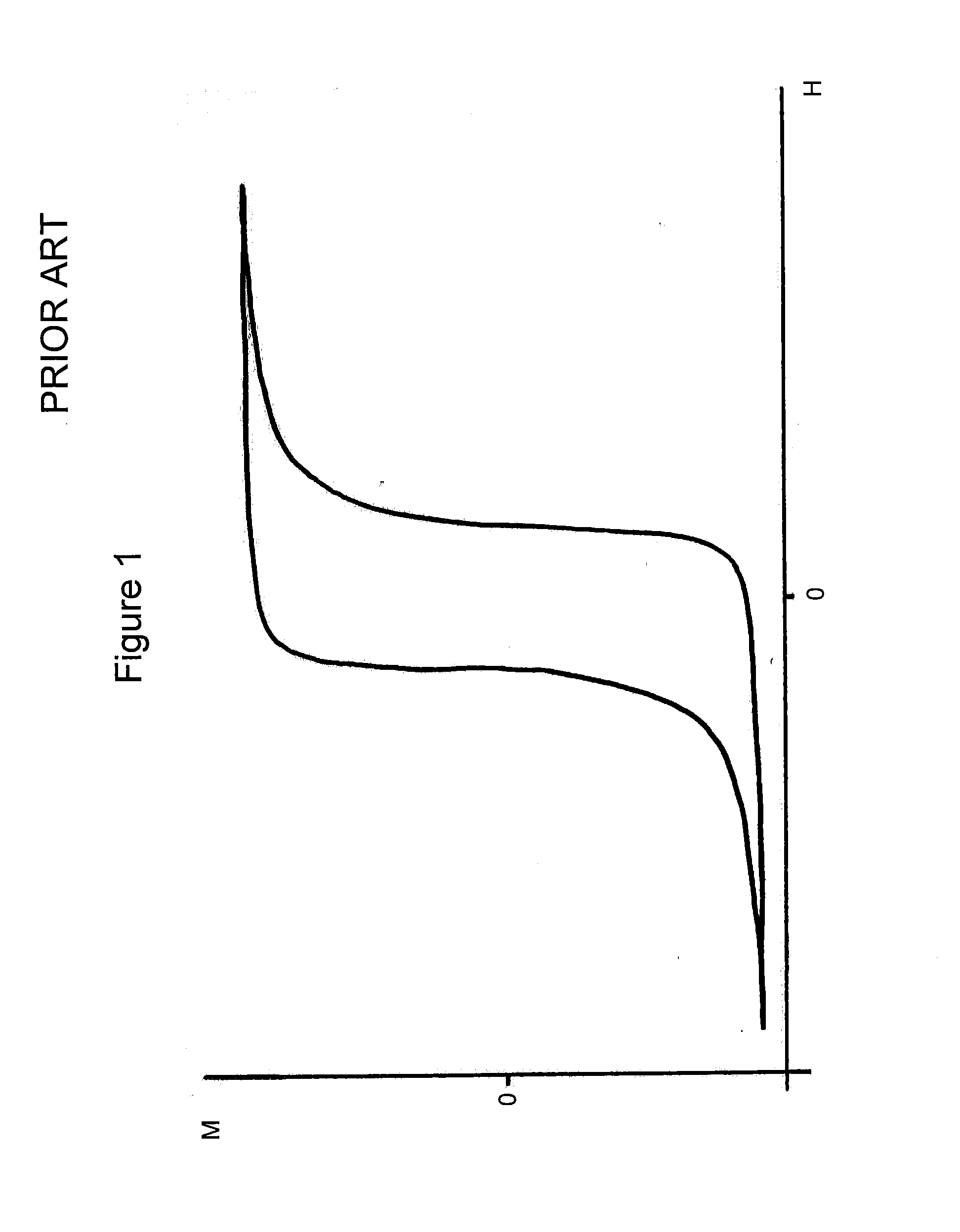
However, when the magnetic field is ramped over time the superconducting coils produce heat.
The required electrical ramping of the magnetic field over time therefore causes heat losses and inefficiency.
This would significantly raise costs.
Further, the faster the ramping rate the higher the required voltage.
Faster ramping requires high voltage power supplies that are not readily available in a form suitable for powering superconducting magnets.
Further, upgrading the speed capability of existing equipment would require either expensive new magnets or an expensive rebuild of the existing magnets.
In addition to the above problems, the ramping magnetic field creates time-varying fringe fields that can adversely affect any nearby equipment or experiments.
However, this system still suffers from the other drawbacks discussed above.

Method used


Image

  • Apparatus for testing sample properties in a magnetic field
  • Apparatus for testing sample properties in a magnetic field
  • Apparatus for testing sample properties in a magnetic field

Examples


Embodiment Construction

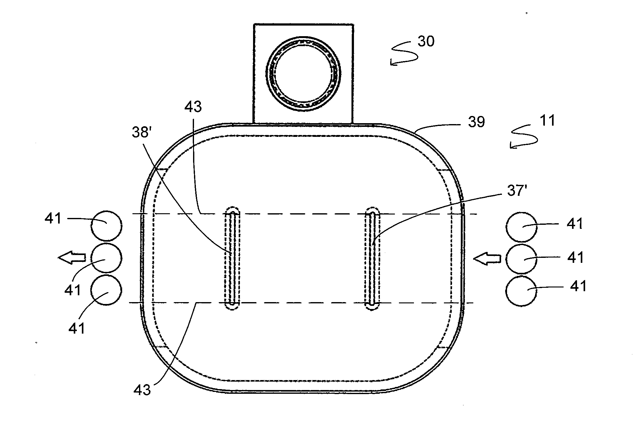
[0137]FIG. 3 is a schematic diagram of a testing apparatus 10 according to one embodiment. The apparatus 10 includes a magnet assembly 11, sample holder 12 and optical arrangement 13. A sample 14 is shown mounted on the sample holder 12.

[0138]The magnet assembly 11 includes an upper portion 15 and a lower portion 16, which include first magnetic poles 18, 18′ and second magnetic poles 19, 19′. As shown in FIG. 3, each pole extends from a base into a central region, and is surrounded by a space 20 in which electromagnet coils (not shown in FIG. 3) are arranged.

[0139]The magnet assembly is operated at fixed current. This means that the magnetic field within the magnet assembly is constant, or static, over time.

[0140]The first magnetic poles 18, 18′ may define a region 21 of minimum magnetic field (Bmin). The second magnetic poles 19, 19′ may have opposite polarity to the first magnetic poles 18, 18′, in which case they will define a region 22 of maximum magnetic field (Bmax). The firs...


PUM


Abstract

A magnetic testing apparatus includes a magnet assembly with a sample path extending through the magnet assembly. The magnetic field produced by the magnet assembly defines a known, varying magnetic field profile along the sample path. A sample is moved along sample path such that the sample portion is subjected to a predetermined magnetic field ramp or magnetic field profile during a measurement period. A measurement arrangement is also provided to measure one or more properties of the sample during the measurement period, in order to test sample properties at a plurality of different magnetic fields. The apparatus may be particularly suited to magneto-optical measurements, including Magneto-Optical Kerr Effect measurements. The apparatus may be used for testing of hard disk platters.

Description

FIELD OF THE INVENTION[0001]The invention relates to testing of samples, particularly but not exclusively to magneto-optical testing.BACKGROUND TO THE INVENTION[0002]Hard drive platters are formed from various magnetic materials applied to a substrate disc. Traditional hard drives use magnetic materials that can be read and written by a magnetic read / write head. However, other technologies have been suggested. In particular HAMR (Heat Assisted Magnetic Recording) materials use a thermally assisted write mechanism. This allows magnetic materials with relatively high coercivity to be used, with smaller bit sizes and higher storage density. In order to write to the disk, a laser beam is used to heat the magnetic material above the Curie temperature. The coercivity drops above this temperature, and a magnetic write field can be used to write data onto the disk. HAMR materials are a good candidate for future advances in hard drive technology.[0003]In testing of hard drive platters, resea...

Claims


Application Information

Patent Timeline
IPC IPC(8): G01R33/032G01N27/72G01N21/21
CPCG01R33/0325G01N27/72G01N21/21G01R33/032G01R33/1207
Inventor FEE, MICHAEL GRAEMEDICKIE, OLIVER JOHN
Owner HTS 110 LTD
Learn More