System and method for calibrating a vision system with respect to a touch probe

a touch probe and vision system technology, applied in the field of machine vision systems, can solve the problems of difficult calibration of the system, difficult to achieve good viewing angle of the camera, and difficulty in using a vision system in conjunction with a touch prob

Active Publication Date: 2016-06-30
COGNEX CORP
View PDF3 Cites 12 Cited by
  • Summary
  • Abstract
  • Description
  • Claims
  • Application Information

AI Technical Summary

Benefits of technology

[0016]In a further illustrative embodiment, an integrated calibration arrangement for calibrating a first vision system camera is provided. The arrangement guides a moving touch probe with respect to a workpiece. The arrangement comprises a base that mounts a second vision system camera and an optics block with a fiducial pattern on an illuminated reticle. The reticle is adapted to selectively contact the touch probe and is also selectively viewed by the first vision system camera. A beam splitter is located in the optical block, which merges an optical path of a source that illuminates the reticle with an optical path of the second vision system camera. In this manner the first vision system camera can locate the viewed reticle in the coordinate space of the touch probe assembly; and the second vision system camera can view the touch probe as it is aligned with the reticle. These two alignments can be coordinated by a processor to calibrate the touch probe with respect to the field of view of the first vision system camera.
[0017]In another embodiment, a vision system camera assembly is provided, with a camera axis mounted with respect to a moving touch probe assembly with a longitudinal axis. A calibration fixture defining a prism assembly bends an optical path by 180 degrees between parallel axes spaced at an offset spacing S, the spacing S being approximately the same as a spacing between the longitudinal axis and the camera axis. An illumination assembly directs illumination into a first prism in the prism assembly through a first face. The first prism includes a top face that confronts a tip of the touch probe assembly. The illumination is reflected twice by total internal reflection and exits the first prism through the first face. The first prism is constructed and arranged so that, when the tip contacts the top face, or resides within a few wavelengths of light above the top face, total internal reflection is frustrated and an evanescent wave couples with the tip, whereby light leaks through the top surface. The leaked light thereby scatters from the tip and reenters the first prism at a near normal (90-degree) angle of incidence to travel through the vision system camera assembly from a contact point of the tip. This allows for relatively precise location of the contact point without (free-of) actually contacting the probe to the prism surface.

Problems solved by technology

A challenge in use of a touch probe in a manufacturing environment—e.g. assembly and / or quality control—is in positioning the touch probe to an appropriate location on the workpiece under inspection.
The use of vision systems in conjunction with a touch probe offer certain challenges in that the locating of the touch point on the touch probe may be obscured during runtime and in general, a good viewing angle for the camera is difficult to attain.
More generally, use of a vision system in conjunction with a touch probe, including calibration of the system is challenging.

Method used


Image

  • System and method for calibrating a vision system with respect to a touch probe
  • System and method for calibrating a vision system with respect to a touch probe
  • System and method for calibrating a vision system with respect to a touch probe

Examples


Embodiment Construction

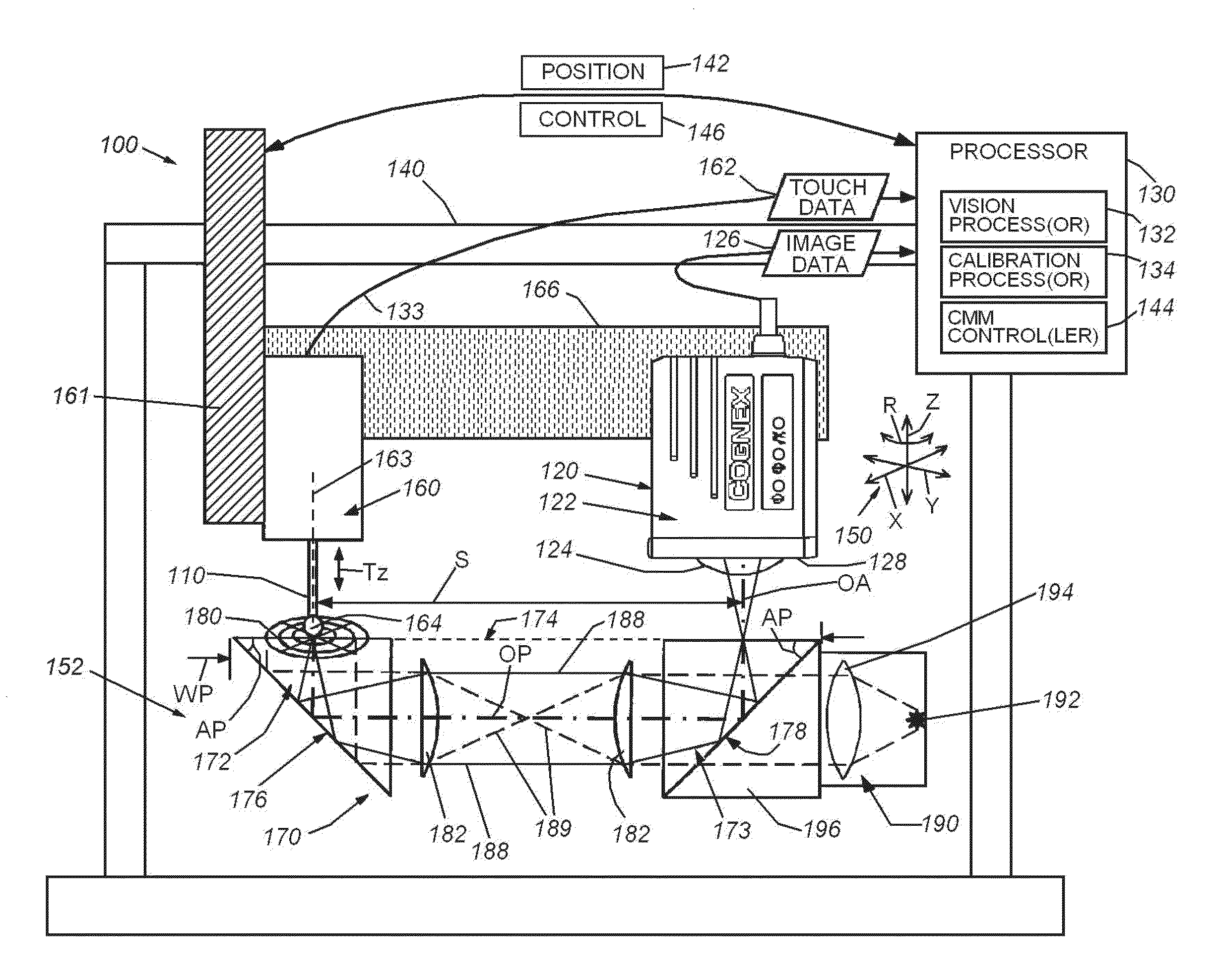
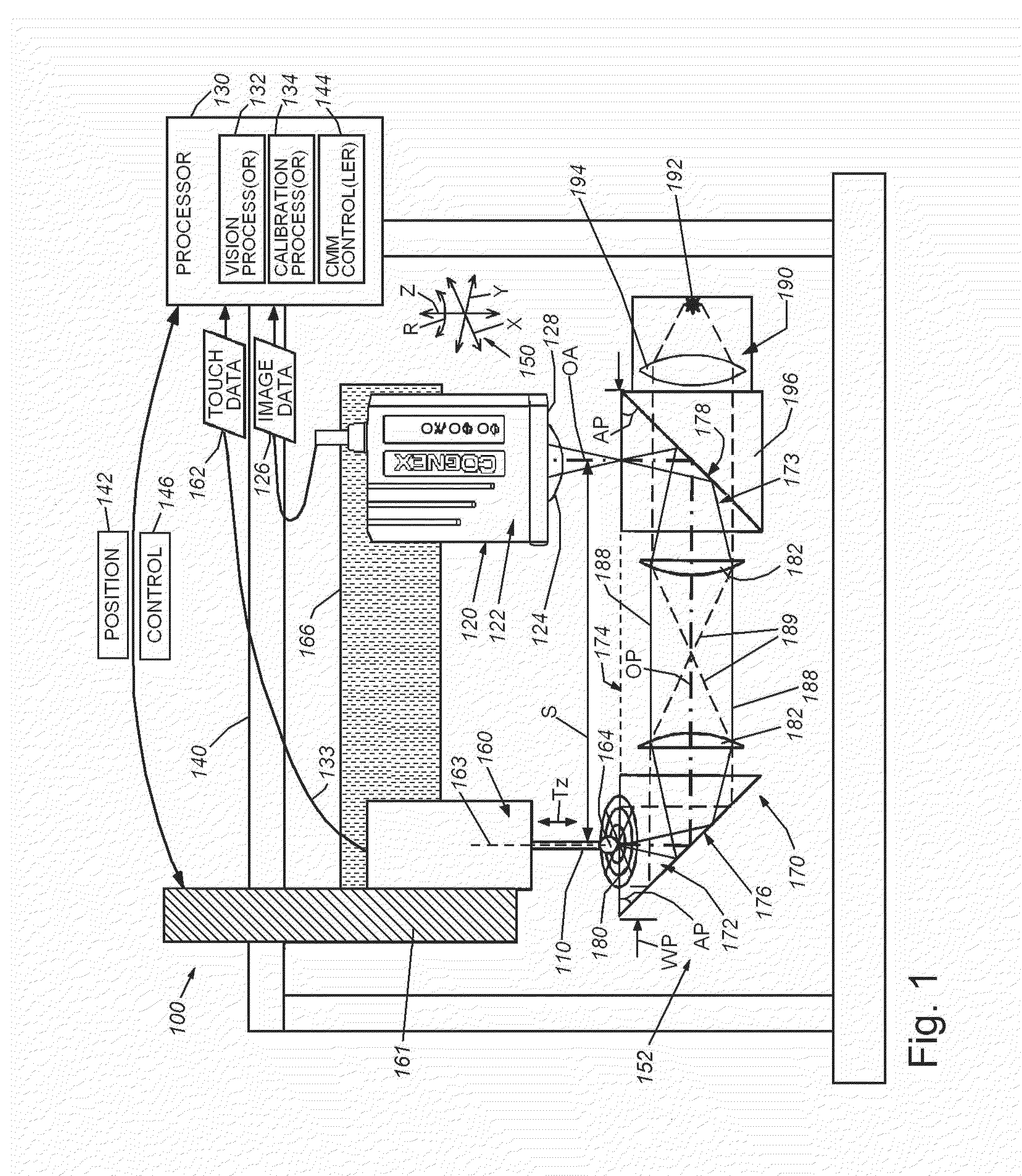
[0034]FIG. 1 details a generalized overview of a manufacturing or inspection arrangement 100. This arrangement can be used for a variety of manufacturing and / or quality control purposes involving workpieces (also termed herein “objects”) that are inspected using a CMM touch probe 110 or similar device. The depicted arrangement 100 includes a vision system 120 having a camera assembly 122 with a lens 124 (shown in phantom) arranged along an optical axis OA. An illumination assembly can be contained in a front face 128 on the camera body, generally to provide illumination to the surface of a workpiece during runtime. As described below, an additional illumination assembly can be located below the target, injecting light through a beamsplitter prism that is part of the arrangement's calibration fixture (170, described below). The camera 122 includes an imager (not shown) that generates image data 126. The image data 126 is transmitted via a wired, wireless and / or internal link 133 to a...


PUM


Abstract

This invention provides a calibration fixture that enables more accurate calibration of a touch probe on, for example, a CMM, with respect to the camera. The camera is mounted so that its optical axis is approximately or substantially parallel with the z-axis of the probe. The probe and workpiece are in relative motion, along a plane defined by orthogonal x and y axes, and optionally the z-axis and/or and rotation R about the z-axis. The calibration fixture is arranged to image from beneath the touch surface of the probe and, via a 180-degree prism structure, to transmit light from the probe touch point along the optical axis to the camera. Alternatively, two cameras respectively view the fiducial location relative to the CMM arm and the probe location when aligned on the fiducial. The fixture can define an integrated assembly with an optics block and a camera assembly.

Description

RELATED APPLICATIONS[0001]This application claims the benefit of U.S. Provisional Application Ser. No. 62 / 111,644, filed Feb. 3, 2015, entitled SYSTEM AND METHOD FOR CALIBRATING A VISION SYSTEM WITH RESPECT TO A TOUCH PROBE, U.S. Provisional Application Ser. No. 62 / 098,894, filed Dec. 31, 2014, entitled SYSTEM AND METHOD FOR CALIBRATING A VISION SYSTEM WITH RESPECT TO A TOUCH PROBE, and U.S. Provisional Application Ser. No. 62 / 067,957, filed Oct. 23, 2014, entitled SYSTEM AND METHOD FOR CALIBRATING A VISION SYSTEM WITH RESPECT TO A TOUCH PROBE, the entire disclosure of each of which applications is herein incorporated by reference.FIELD OF THE INVENTION[0002]This invention relates to machine vision systems and more particularly to calibration of vision systems used in inspection and manufacturing processes.BACKGROUND OF THE INVENTION[0003]In manufacturing and assembly processes, it is often desirable to measure an object surface with a high degree of accuracy. One technique for perf...

Claims


Application Information

Patent Timeline
Patent Type & Authority Applications(United States)
IPC IPC(8): H04N17/00H04N5/232H04N5/247H04N7/18H04N5/225
CPCH04N17/002H04N7/183H04N5/23296H04N5/247H04N5/2253G01B21/042G01B21/20G01B5/20G01B5/012G12B5/00H04N23/54H04N23/69H04N23/90
Inventor FILHABER, JOHN F.JACOBSON, LOWELL D.COSTIGAN, GEORGE J.
Owner COGNEX CORP
Why Eureka
Try Eureka