
Electronic device and image building module thereof

a technology of electronic devices and image building modules, applied in the field of image building modules, can solve problems such as increasing antenna noise, and achieve the effect of reducing antenna nois

Active Publication Date: 2016-06-30
PEGATRON
View PDF0 Cites 19 Cited by
  • Summary
  • Abstract
  • Description
  • Claims
  • Application Information

AI Technical Summary

Benefits of technology

The invention aims to prevent the image building module from interfering with the signals of the antenna, which can reduce the noise of the antenna. This is achieved by using a signal-shielding flexible film that covers the processing chip and image builder, minimizing interference during operation. Overall, the invention prevents interference between the image building module and the antenna, resulting in improved signal quality.

Problems solved by technology

However, when the image building module operates, it easily interferes with signals of the antenna thus to increase the noise of the antenna.

Method used


Image

  • Electronic device and image building module thereof
  • Electronic device and image building module thereof
  • Electronic device and image building module thereof

Examples


Embodiment Construction

[0023]The following drawings disclose several embodiments of the present invention, and for clear illustration, many details of the practice may be described in the following description. However, persons in the art should understand that the practical details are not essential in some embodiments and therefore they are not used to limit the present invention. In addition, to simplify the drawings, some conventional structures and elements in the drawings may be depicted in a simple method. Further, to facilitate reading, each element in the drawings is not depicted in the original dimension.

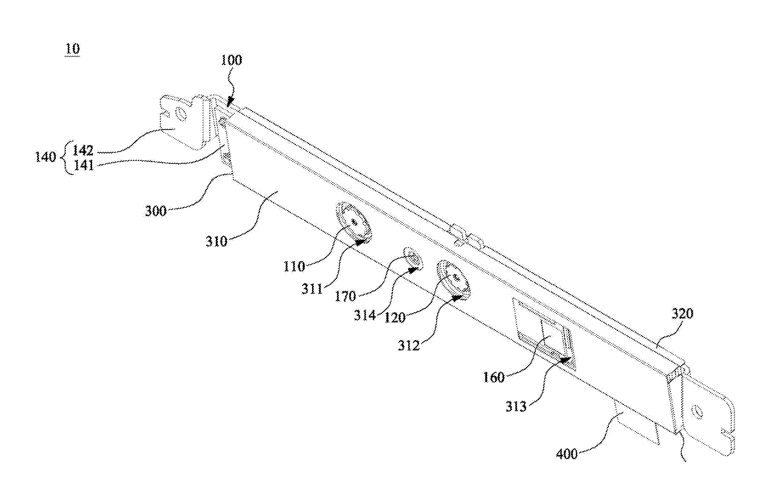
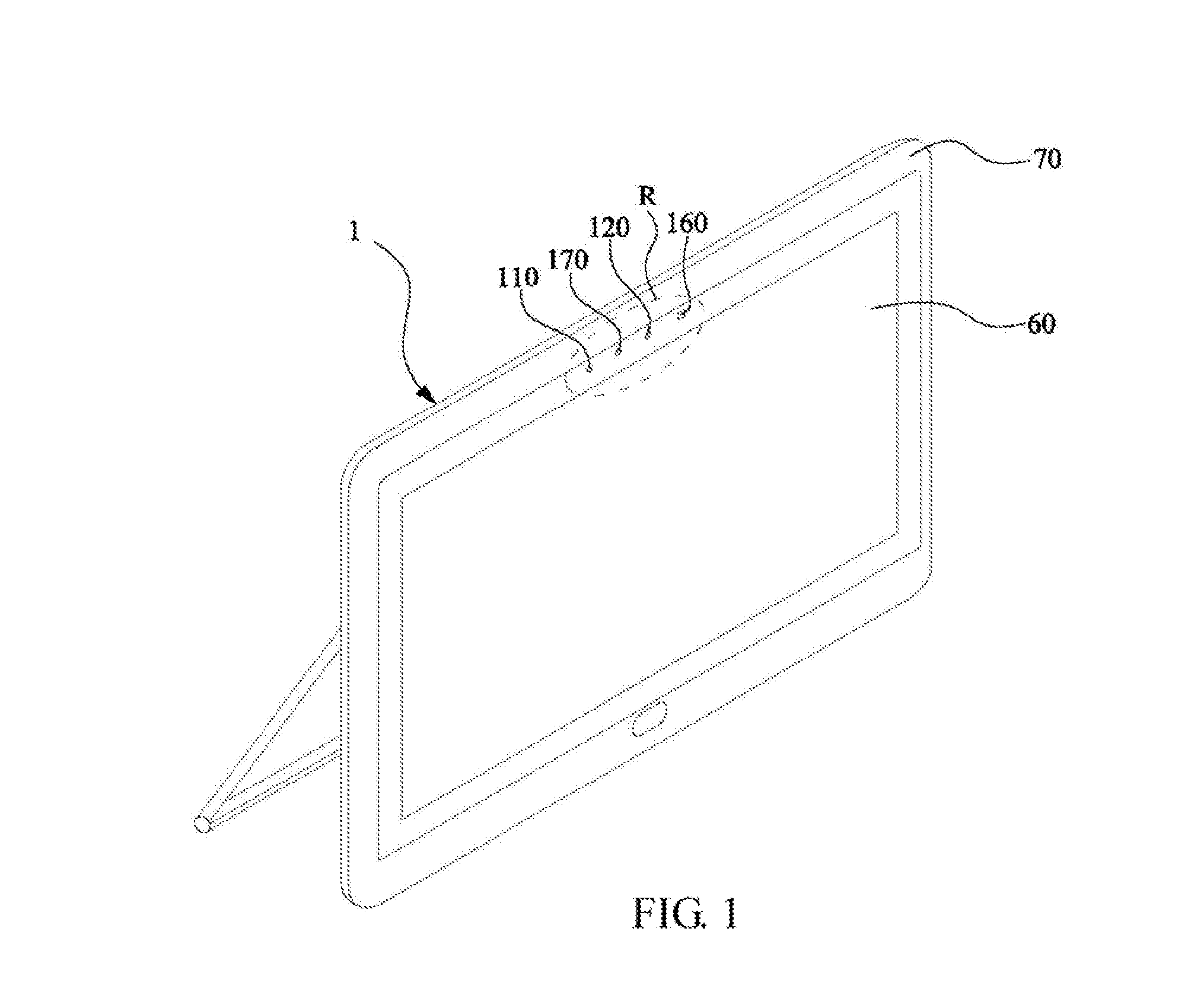
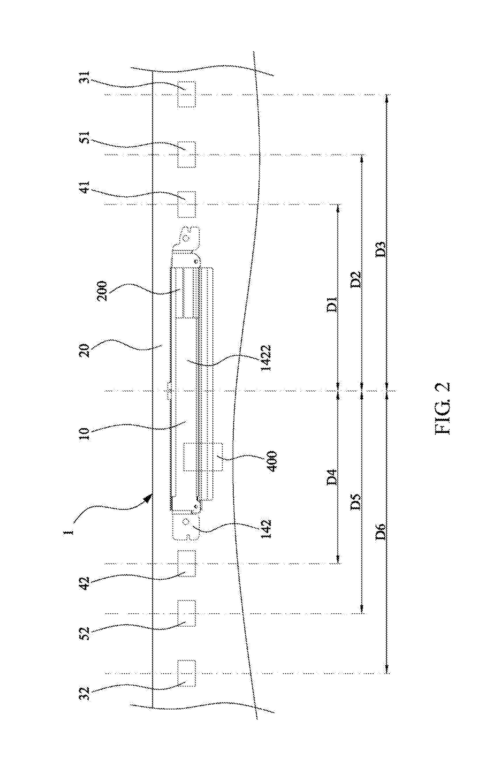
[0024]FIG. 1 is a three-dimensional diagram of an electronic device according to one embodiment of the invention. FIG. 2 is a top view of the interior of a local area of the electronic device in FIG. 1. In FIG. 2, the electronic device 1 includes an image building module 10, a substrate 20, and an antenna 31. The image building module 10 may be a camera module including an image capturing elemen...


PUM


Abstract

An image building module includes an image builder, a signal-shielding flexible film, and a signal shielding cover. The image builder includes a first image capturing element and a processing chip. The first image capturing element is used for capturing a first image. The processing chip is used for processing the first image. The signal-shielding flexible film covers the processing chip. The signal shielding cover covers the image builder and the signal-shielding flexible film. The signal shielding cover has a first through hole exposing the first image capturing element.

Description

CROSS-REFERENCE TO RELATED APPLICATIONS[0001]This Non-provisional application claims priority under 35 U.S.C. §119(a) on Patent Application No(s). 103145773 filed in Taiwan, Republic of China on Dec. 26, 2014, the entire contents of which are hereby incorporated by reference.BACKGROUND[0002]1. Technology Field[0003]This disclosure relates to an image building module.[0004]2. Description of the Related Art[0005]Generally speaking, at present, many electronic devices such as notebook computers, all-in-one PCs, tablet computers and so on are provided with front lenses to allow users to capture images or to make films. The electronic devices also include antenna modules wirelessly connected with Internet, thus allowing the users to browse the Internet and to upload the images or films to the Internet as well.[0006]With the development of the multimedia technology, stereoscopic images attract more and more attention. Further, at present, parts of the electronic devices use image building...

Claims


Application Information

Patent Timeline
IPC IPC(8): H04N5/225H04N13/02H04N13/239
CPCH04N5/2254H04N13/0239H04N5/2257H01Q1/22H01Q1/526H04N13/239H04N23/57G06F1/1686H01Q1/52
Inventor YEH, TSUNG-CHIHWANG, TUNG-LIANGKAO, PI-MINLEE, HSUN-HSINKUO, CHUN-HAO
Owner PEGATRON
Learn More