
Interior-permanent-magnet motor structure

a permanent magnet, motor technology, applied in the direction of windings, magnetic circuit rotating parts, magnetic circuit shape/form/construction, etc., can solve the problems of poor and unstable operation performance of the motor, limited enhancement of the motor performance, and limited reduction of cogging force, so as to achieve smooth operation

Inactive Publication Date: 2016-06-30
HIWIN MIKROSYST
View PDF3 Cites 11 Cited by
  • Summary
  • Abstract
  • Description
  • Claims
  • Application Information

AI Technical Summary

Benefits of technology

The patent is about improving the operation of an interior-permanent-magnet motor by making the air gap magnetic flux in a better state. This results in a more smooth operation of the motor and reduces the cogging force effect.

Problems solved by technology

Under such circumstance, the operation performance of the motor is poor and unstable.
However, it can be known from the curve of FIG. 4 that the enhancement of the performance of the motor is still limited.
Also, the reduction of the cogging force is limited.

Method used


Image

  • Interior-permanent-magnet motor structure
  • Interior-permanent-magnet motor structure
  • Interior-permanent-magnet motor structure

Examples


Embodiment Construction

[0027]Please refer to FIGS. 5 and 6. According to a preferred embodiment, the interior-permanent-magnet motor structure 10 of the present invention is an interior-permanent-magnet motor with improved air gap space based on the conventional V-shaped interior-permanent-magnet motor. The interior-permanent-magnet motor structure 10 includes a rotor member 20, a stator member 30 and an annular air gap 40.

[0028]The rotor member 20 has a rotor seat 21. Multiple insertion cavities 22 with elongated cross section are respectively disposed in the rotor seat 21 in pair. The insertion cavities 22 are lengthwise arranged in V-form. The opening of the V-form is positioned with its back to the curvature center α of the rotor seat 21. Multiple magnetic bodies 23 with elongated cross section are respectively inlaid in the insertion cavities 22. The volume of the magnetic body 23 is smaller than the capacity of the insertion cavity in which the magnetic body is inlaid. Two ends of the magnetic body ...


PUM


Abstract

An interior-permanent-magnet motor structure includes an air gap having the form of an annular band. The air gap is positioned between the stator and the rotor. The width of the annular band of the air gap has a maximum value and a minimum value within each pole pitch range. Accordingly, the air gap magnetic flux is nearly in sine wave state.

Description

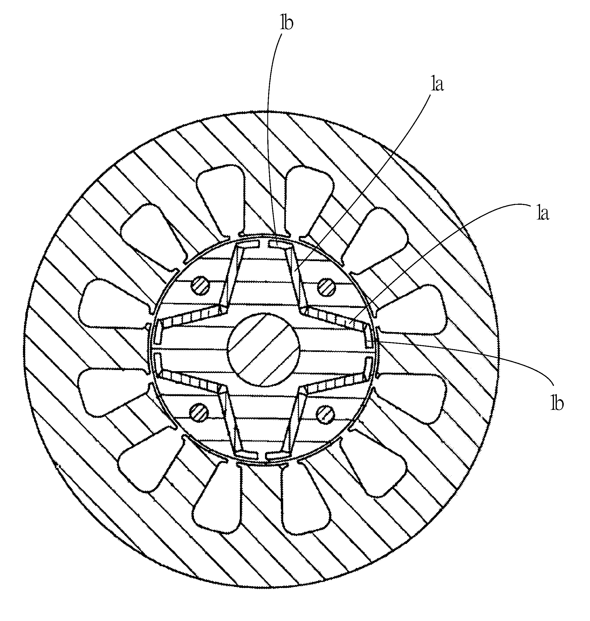
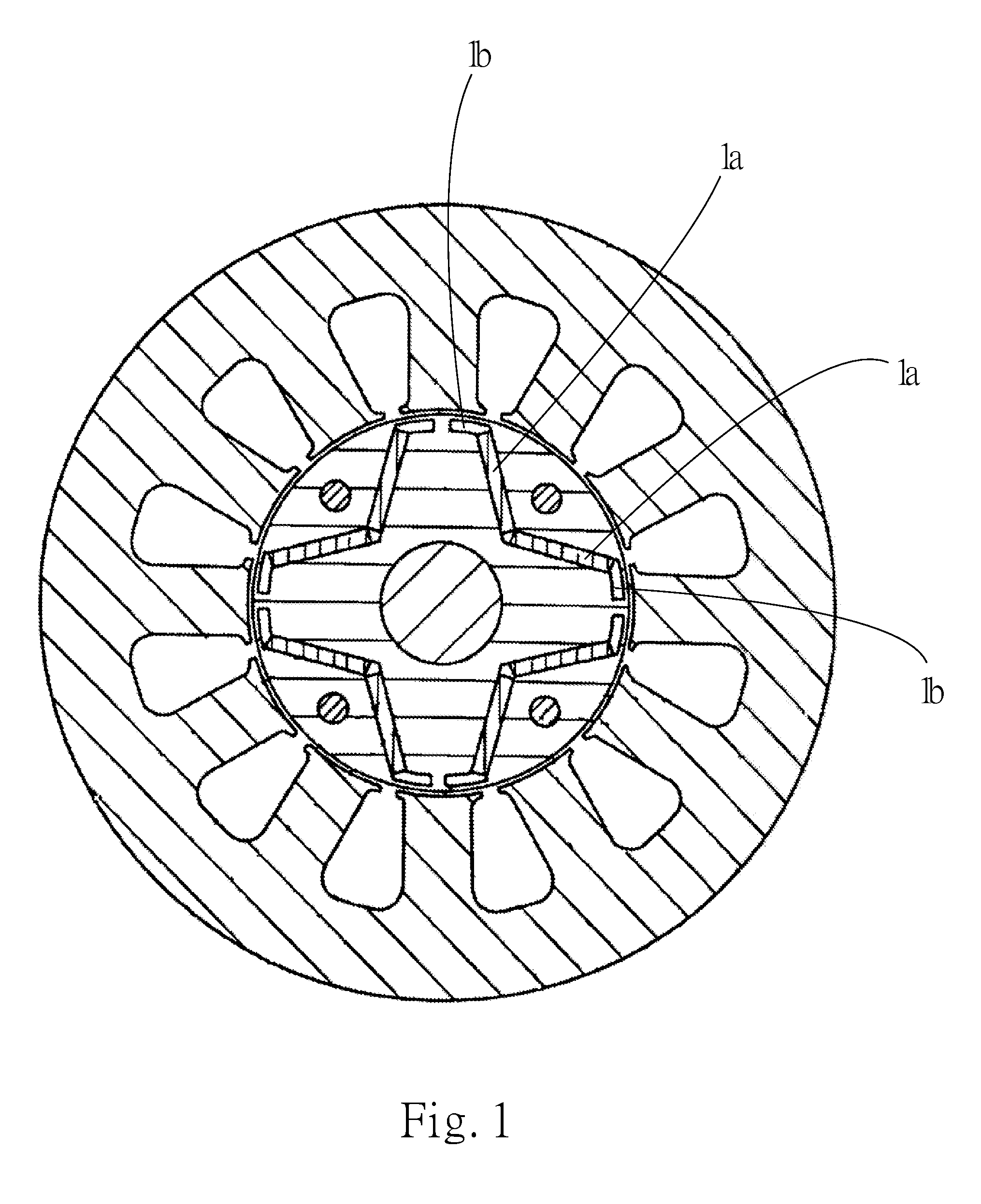
BACKGROUND OF THE INVENTION[0001]1. Field of the Invention[0002]The present invention relates generally to a motor, and more particularly to an improved interior-permanent-magnet motor structure.[0003]2. Description of the Related Art[0004]In an interior-permanent-magnet motor, the permanent magnets are embedded in the iron core of the rotor and enclosed by the iron core. Therefore, the interior-permanent-magnet motor has better mechanical reliability and is suitable for high-speed operation. FIG. 1 shows an improved conventional interior-permanent-magnet motor having higher performance. In the interior-permanent-magnet motor, voids are formed between the magnetic bodies la of two poles in the rotor and two sides of outer circumference of the rotor so as to avoid magnetic short-circuit effect. Also, the voids serve to enhance the rotational torque and reduce cogging force so as to achieve damping and noise-lowering effect.[0005]The spaces of the voids 1b provide magnetic resistance ...

Claims


Application Information

Patent Timeline
Patent Type & Authority Applications(United States)
IPC IPC(8): H02K1/27H02K3/00
CPCH02K3/00H02K1/276H02K29/03H02K2201/03H02K2213/03
Inventor ZHENG, LI-WEILU, PING-SHIUNLIN, WEI-PING
Owner HIWIN MIKROSYST
Learn More