Eureka AIR delivers breakthrough ideas for toughest innovation challenges, trusted by R&D personnel around the world.

Systems and methods for providing a frequency sensitive surface antenna

Inactive Publication Date: 2016-06-30
RUCKER DON +2
View PDF1 Cites 8 Cited by
  • Summary
  • Abstract
  • Description
  • Claims
  • Application Information

AI Technical Summary

Benefits of technology

The present invention provides a wideband antenna device and method that improves RF reception and transmission for electronic devices using RF communication means. It uses a unique ground plane configuration and construction that maximizes the radiated and received RF signals through the antenna element, across substantially the bandwidth served by the wideband antenna. The device is designed with a dual layer ground plane configured to maximize broadcast and reception performance across the entire spectrum of the antenna. The method allows for the configuration of multiple layer ground planes that are tuned to the frequency ranges of an adjacent wideband antenna to maximize gain across those frequencies. Overall, the invention solves the shortcomings in prior art in wideband antennas formed on planar substrate which employ a ground plane.

Problems solved by technology

However, the type of wireless communication provided by a grid or other source is only useful when the receiving user device is able to receive transmissions, and the cell tower antenna can receive transmissions from the low-powered devices of remote users.
Even with the advancements in the technology of smart phones and other devices, users often continue to experience poor cellular reception.
Cellular providers are often limited to the quantity and location of which a cellular grid can be built.
Therefore, adding more or constructing larger grids to provide improved cellular reception to customers is often limited.
There has not been a highly signal sensitive and easily constructed for retrofit or for employment on wireless communications towers such as cellular antennas which is adapted to maximize reception from across a broadband of RF frequencies, which has excellent reception and throughput at both lower and higher frequencies.
Most such antennas are either dipole antennas with limited wideband capability.
However, many such wideband antennas which can suffer signal loss or poor performance at the lower or higher ends of the RF spectrum served, due to aspects of physical construction.
Consequently, they may not provide optimum RF reception and transmission at all frequencies or bands for which the antenna is capable.
Thus, while techniques currently exist relating to wireless technologies, challenges still exist.

Method used


Image

  • Systems and methods for providing a frequency sensitive surface antenna
  • Systems and methods for providing a frequency sensitive surface antenna
  • Systems and methods for providing a frequency sensitive surface antenna

Examples


Embodiment Construction

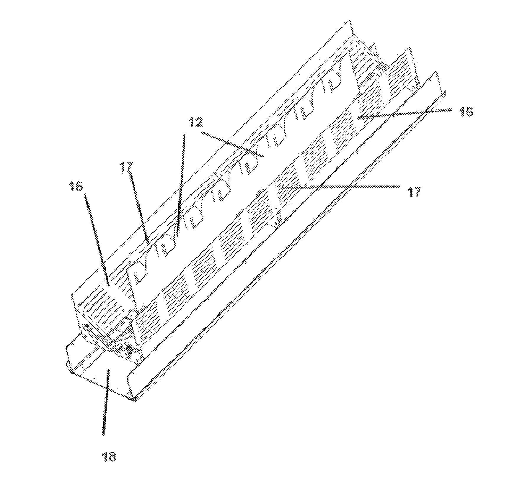
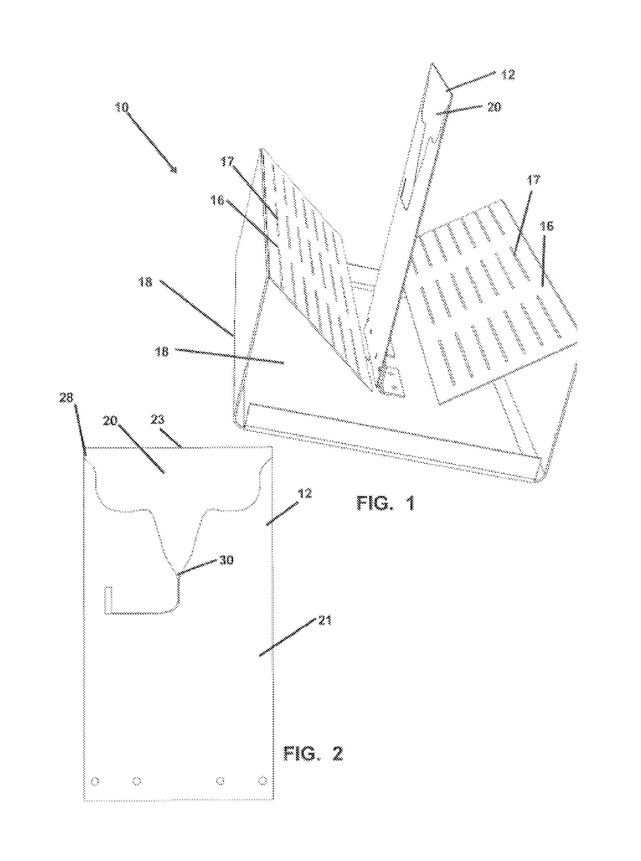
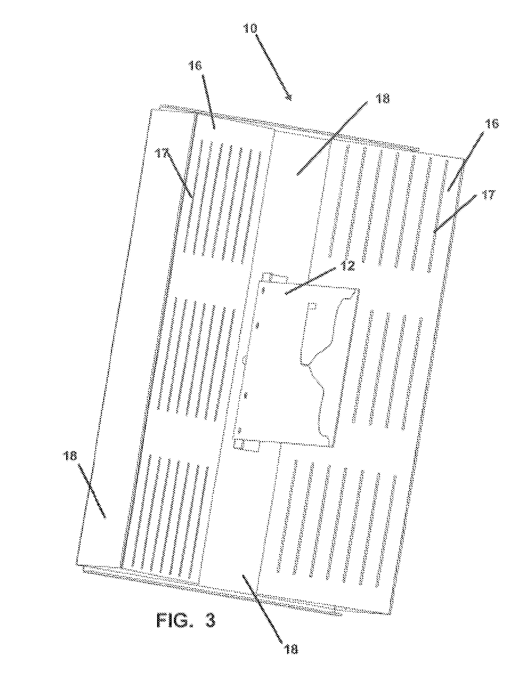
[0039]The present invention relates generally to antennas employed in radio frequency (RF) transmission and communication. More particularly, the invention relates to a multi-surface ground plane device and method for a wideband antenna which employs a frequency selective surface to optimize higher frequencies within the range of the wideband antenna and is especially well adapted for cellular communications for both data and voice but can be employed with any horn style wideband antenna.

[0040]In this description, the directional prepositions of up, upwardly, down, downwardly, front, back, top, upper, bottom, lower, left, right and other such terms refer to the device as it is oriented and appears in the drawings and are used for convenience only. The employment of such terms thus is not intended to be limiting or to imply that the device has to be used or positioned in any particular orientation.

[0041]Now referring to drawings in FIGS. 1-9, wherein similar components are identified...


PUM


Abstract

Systems and methods for providing a multi-surface ground plane device for a wideband antenna which employs a frequency selective surface to optimize higher frequencies within the range of the wideband antenna and is especially well adapted for cellular communications for both data and voice but can be employed with any horn style wideband antenna.

Description

RELATED APPLICATIONS[0001]This application claims priority to U.S. Provisional Patent Application Ser. No. 62 / 024,895 filed Jul. 15, 2014, entitled FREQUENCY SENSITIVE SURFACE ANTENNA, which is incorporated herein by reference.BACKGROUND OF THE INVENTION[0002]1. Field of the Invention[0003]The present invention relates generally to antennas employed in radio frequency (RF) transmission and communication. More particularly, the invention relates to a multi-surface ground plane device and method for a wideband antenna which employs a frequency selective surface to optimize higher frequencies within the range of the wideband antenna and is especially well adapted for cellular communications for both data and voice but can be employed with any horn style wideband antenna.[0004]2. Background and Related Art[0005]Electronic devices such as smart phones, cell phones, laptops, tablets, and the like conventionally communicate with cellular towers, computer networks, internet modems, Bluetoot...

Claims


Application Information

Patent Timeline
IPC IPC(8): H01Q13/08H01Q1/24H01Q1/48
CPCH01Q13/085H01Q1/246H01Q1/48H01Q15/0013H01Q19/106H01Q21/08
Inventor RUCKER, DONWESTBERG, RONNASH, PHIL
Owner RUCKER DON
Why Eureka
Eureka Blog
Learn More