
Power steering apparatus and preload adjustment method thereof

a technology of preload adjustment and power steering, which is applied in the direction of gearing details, manufacturing tools, transportation and packaging, etc., and can solve problems such as variation

Active Publication Date: 2016-06-30
HITACHI ASTEMO LTD
View PDF2 Cites 7 Cited by
  • Summary
  • Abstract
  • Description
  • Claims
  • Application Information

AI Technical Summary

Benefits of technology

The present invention allows for adjusting the preload between the worm and worm wheel to a desired value regardless of manufacturing and assembly errors. This is achieved by providing a plug fixing member that fixes the position of the plug to the screwing position. The technical effect is the ability to achieve a desired preload between the worm and worm wheel.

Problems solved by technology

However, variation may occur in the distance between the position of the worm and the lid attachment surface, the free length of the spring and the like due to manufacturing errors, assembly errors and so on.

Method used


Image

  • Power steering apparatus and preload adjustment method thereof
  • Power steering apparatus and preload adjustment method thereof
  • Power steering apparatus and preload adjustment method thereof

Examples


first embodiment

[Structure of Motor-Driven Power Steering Apparatus]

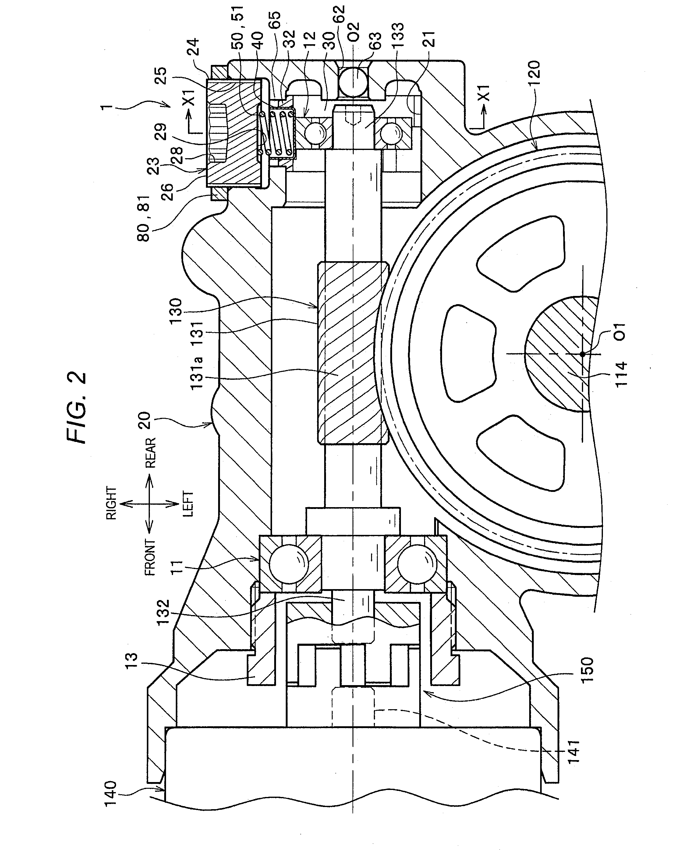
[0030]In FIG. 1, a motor-driven power steering apparatus 100 (steering apparatus) is a pinion assist type apparatus in which an assist force is inputted to a pinion shaft 114. However, the present invention can be also applied to a column-assist type and a rack-assist type motor-driven power steering apparatuses.

[0031]A motor-driven power steering apparatus 100 includes a steering wheel 111 operated by a driver, a steering shaft 112 rotating together with the steering wheel 111, a torsion bar 113 connected to a lower end of the steering shaft 112, a pinion shaft 114 connected to a lower end of the torsion bar 113 and a rack shaft 115 extending in a vehicle width direction (right and left direction).

[0032]Pinion teeth 114a of the pinion shaft 114 are meshed with rack teeth 115a of the rack shaft 115. Then, when the pinion shaft 114 rotates around a rotation axis O1 (see FIG. 2), the rack shaft 115 moves in the vehicle width directio...

second embodiment

[0059]A second embodiment will be explained with reference to FIGS. 6A and 6B. The second embodiment is an embodiment in which the plug fixing member 80 is formed by caulking between the plug 23 and the housing 20. As the other components are the same as those of the first embodiment, the explanation thereof is omitted.

[0060]On an outer surface of the housing 20 around the female screw 25, protrusions 82 for caulking are formed so as to protrude as shown in FIG. 6A. Plural protrusions 82 may be provided at intervals in a circumferential direction of the female screw 25 as well as one protrusion 82 may be provided. In the plug 23 of the present embodiment in which the position is adjusted so as to obtain the desired preload between the worm 130 and the worm wheel 120, the outer end surface 26 is approximately flush with the outer surface of the housing 20. When the protrusions 82 are bent to the inner diameter side by using a not-shown jig, the protrusions 82 bite into the plug 23 by...


PUM


Abstract

A power steering apparatus includes: a worm driven by a motor for assistance; a worm wheel engaged with the worm and transmitting an assist force to a steering shaft; a housing which houses the worm and the worm wheel; a plug having a male screw on an outer peripheral surface of the plug, the male screw being screwed with a female screw formed at the housing; an elastic member, one end of which in a biasing direction of the elastic member is supported by the worm and other end of which in the biasing direction is supported by the plug, giving a preload between the worm and the worm wheel; and a plug fixing member for fixing the plug, a position of which is adjusted to a screwing position at which the preload is a predetermined value, so that the plug is unrotatable with respect to the housing.

Description

CROSS-REFERENCE TO RELATED APPLICATIONS[0001]This application is based on and claims priority under 35 USC 119 from Japanese Patent Application No. 2014-260205 filed on Dec. 24, 2014, the content of which is incorporated herein by reference.BACKGROUND OF THE INVENTION[0002]1. Field of the Invention[0003]The present invention relates to a power steering apparatus and a preload adjustment method thereof.[0004]2. Description of Related Art[0005]In a motor-driven power steering apparatus, a rotation force of a motor for assistance generating an assist force is generally transmitted through a speed reduction mechanism to a pinion shaft and so on connected to a steering shaft through a torsion bar. The speed reduction mechanism is formed by, for example, a worm gear mechanism. In the case where the motor-driven power steering apparatus is a pinion-assist type apparatus, the speed reduction mechanism is formed by including a worm connected to an output shaft of a motor and a worm wheel fix...

Claims


Application Information

Patent Timeline
Patent Type & Authority Applications(United States)
IPC IPC(8): B62D3/06B62D5/04
CPCB62D3/06B62D5/0403B62D5/0454B62D5/0421F16H57/12B62D5/0409
Inventor NOGUCHI, SATOSHI
Owner HITACHI ASTEMO LTD
Learn More