
Human machine interface device for aircraft

Active Publication Date: 2016-06-23
QUAERO +1
View PDF8 Cites 45 Cited by
  • Summary
  • Abstract
  • Description
  • Claims
  • Application Information

AI Technical Summary

Benefits of technology

The patent text describes how touch screen technology can be used in the cockpit to provide better convenience, comfort, and communication with the aircraft systems. This technology can also improve situational awareness, reduce costs, and increase safety for piloted vehicles. Additionally, the method can provide tactile feedback by creating actual buttons and keypads on the touch screen, which can make the device easier to use in the cockpit.

Problems solved by technology

However, they have a number of drawbacks.
The large number of functions that need to be accessed by the pilot results in a large space needed for buttons, switches and knobs in the cockpit.
This results in such devices being located all around the pilot, which is sub-optimal and, in certain cases, even being out of reach of the pilot and he or she will need to get out of the seat to reach the specific device.
Locating the correct input control and selecting the desired option or value (such as entering a target altitude value in the FCU) can be relatively time-consuming, which is of significance particularly in high workload periods of the flight.
This is inconvenient, especially when actions also involve relatively long operation times and careful selection (such as the selection of a specific large altitude change on the MCP / FCU).
The situation is further compounded when the pilot needs to reach out to operate the device in turbulence conditions, as this makes the action much more difficult to execute correctly.
Also, input devices (such as the control panels and keypads) are expensive pieces of equipment that get damaged and need replacing during the life of the aircraft.
There are other limitations of using buttons, switches and knobs to control the aircraft.
The location and use of buttons, switches and knobs may also limit the aircraft to need to be operated by two crew members under normal operating conditions.

Method used


Image

  • Human machine interface device for aircraft
  • Human machine interface device for aircraft
  • Human machine interface device for aircraft

Examples


Embodiment Construction

[0049]Various example embodiments will now be described more fully with reference to the accompanying drawings.

[0050]Detailed illustrative embodiments are disclosed herein. However, specific structural and functional details disclosed herein are merely representative for purposes of describing example embodiments. This invention may, however, be embodied in many alternate forms and should not be construed as limited to only the embodiments set forth herein.

[0051]Accordingly, while example embodiments are capable of various modifications and alternative forms, the embodiments are shown by way of example in the drawings and will be described herein in detail. It should be understood, however, that there is no intent to limit example embodiments to the particular forms disclosed. On the contrary, example embodiments are to cover all modifications, equivalents, and alternatives falling within the scope of this disclosure. Like numbers refer to like elements throughout the description of...


PUM


Abstract

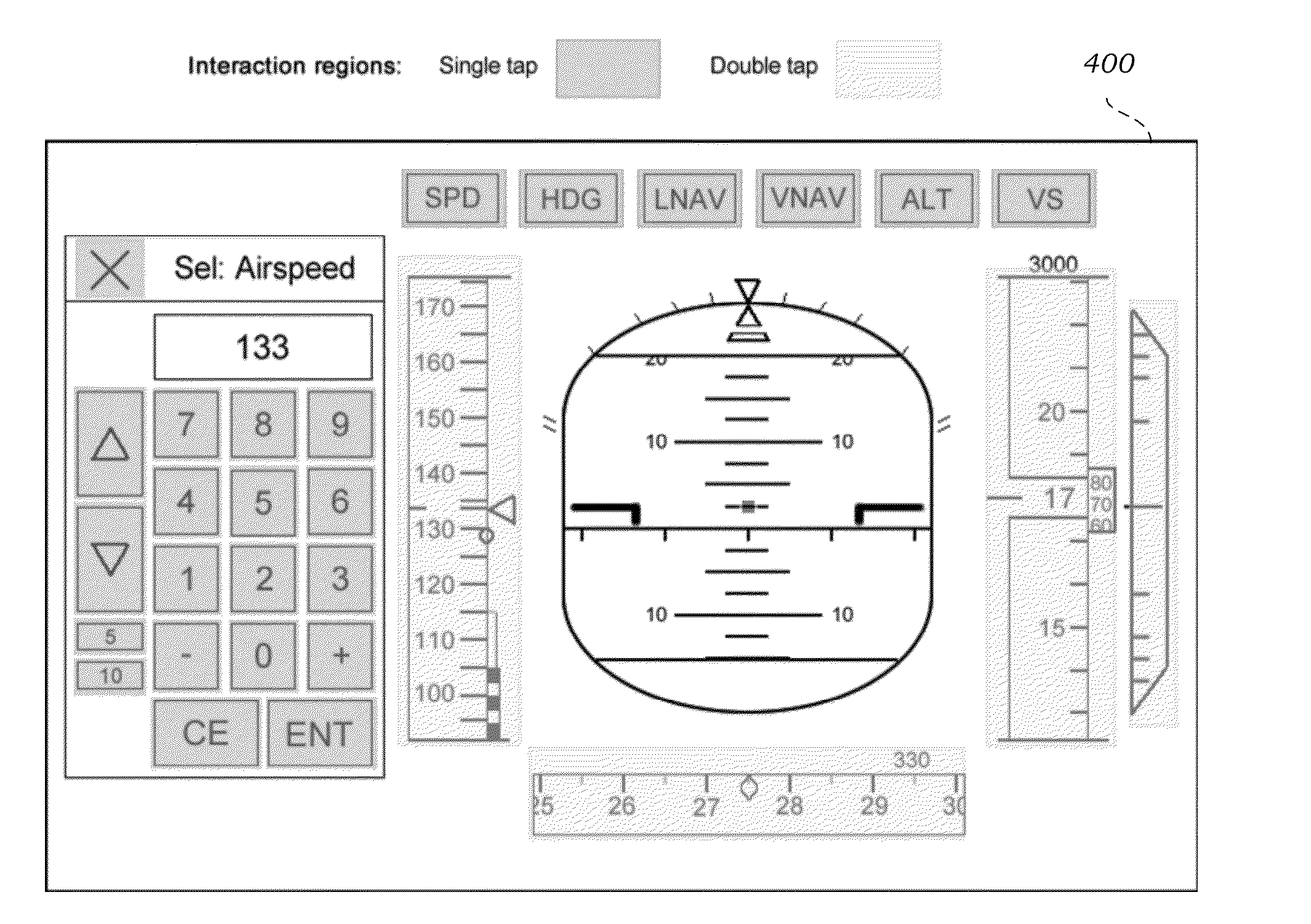
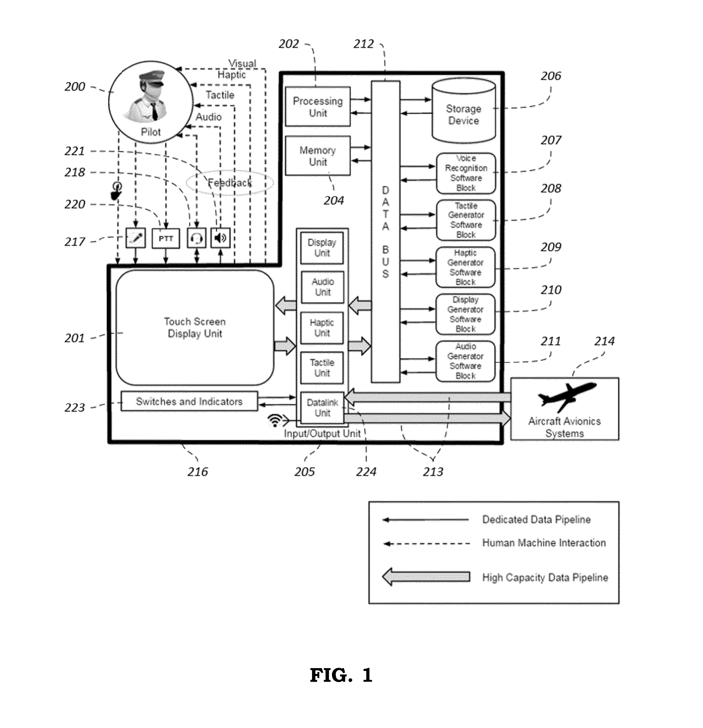
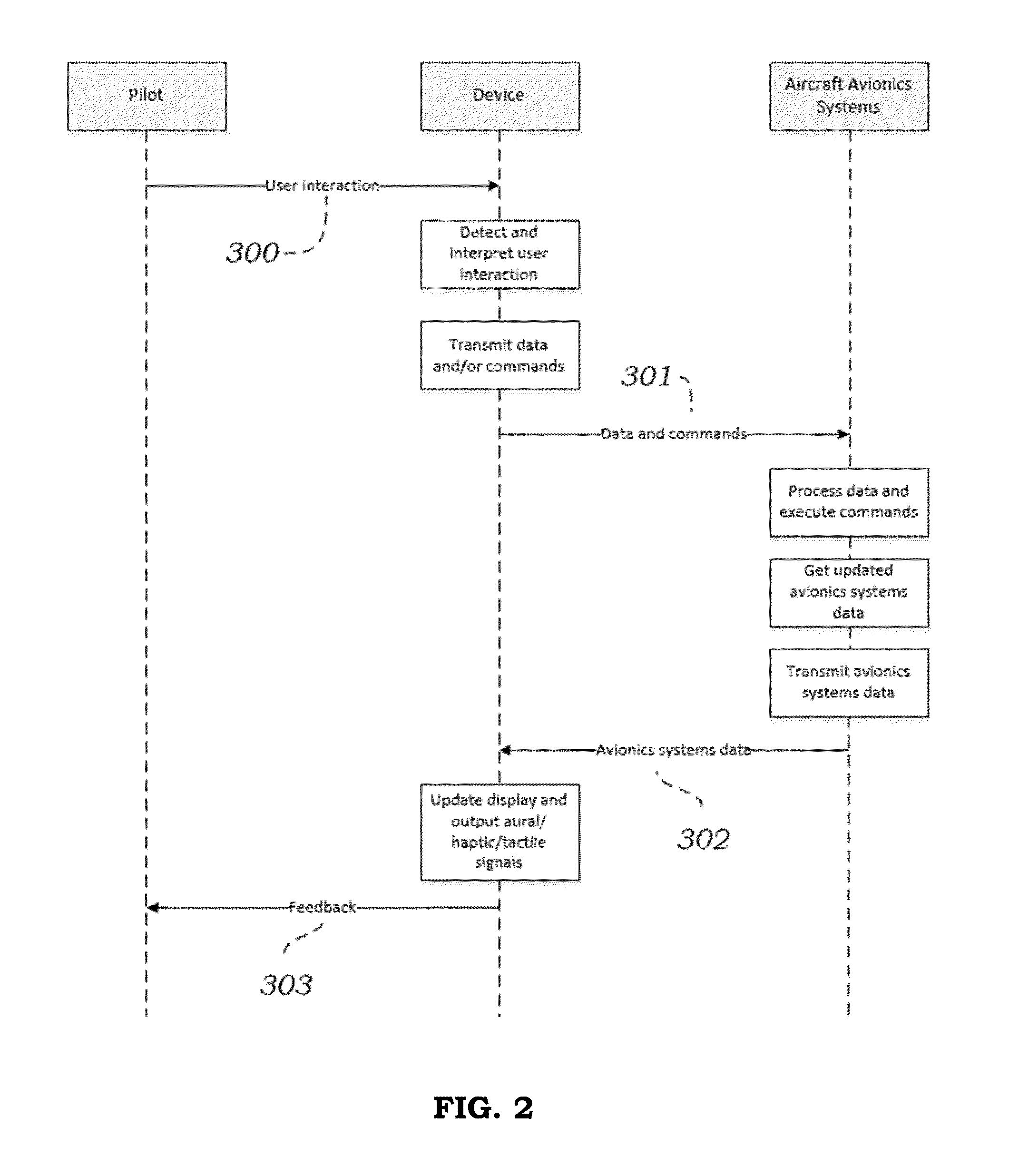
A method and system for interacting with the systems of an aircraft using touch screen technology that includes a human machine interface device for interacting with aircraft systems. The human machine interface including an input / display device configured to provide for navigating among graphical representations of a plurality of aircraft avionics systems via the common human machine interface; selecting an aircraft system via at least one of a touch gesture and a voice command input to the input / display device; inputting an instruction to the selected aircraft system; and outputting information via at least one of visual, aural, haptic and tactile channels.

Description

FIELD OF THE INVENTION[0001]The present invention relates to a human machine interface device for interacting with aircraft systems.BACKGROUND OF THE INVENTION[0002]Touch screen technologies have completely changed the way humans interact with different systems and their use is prevalent in several sectors, including the consumer market (mobile phones, tablets, etc.), the automotive industry, the banking sector, and the medical sector. Users can interact with the display by using their fingertips in a variety of single and multi-touch gestures.[0003]Despite the popularity of touch screen technologies, their use within the cockpit environment of modern civil aircraft, as a method of interacting with avionic systems, is still relatively new. The majority of interactions between pilots and the various aircraft systems still take place via devices such as knobs, switches and keypads located mainly on the glare shield and on the central pedestal of an aircraft's flight deck. However, wit...

Claims


Application Information

Patent Timeline
IPC IPC(8): G06F3/0488B64D43/02G08G5/00G05D1/10G06F3/0484G06F3/0482
CPCG06F3/0488G06F3/04847B64D43/02G08G5/0039G05D1/101G06F3/0482G01C23/00G01C23/005
Inventor ZAMMIT-MANGION, DAVIDJEDRUSZEK, MATEUSZMUSCAT, ALAN
Owner QUAERO
Learn More