Vehicle control device

Inactive Publication Date: 2016-06-23
TOYOTA JIDOSHA KK
View PDF22 Cites 0 Cited by
  • Summary
  • Abstract
  • Description
  • Claims
  • Application Information

AI Technical Summary

Benefits of technology

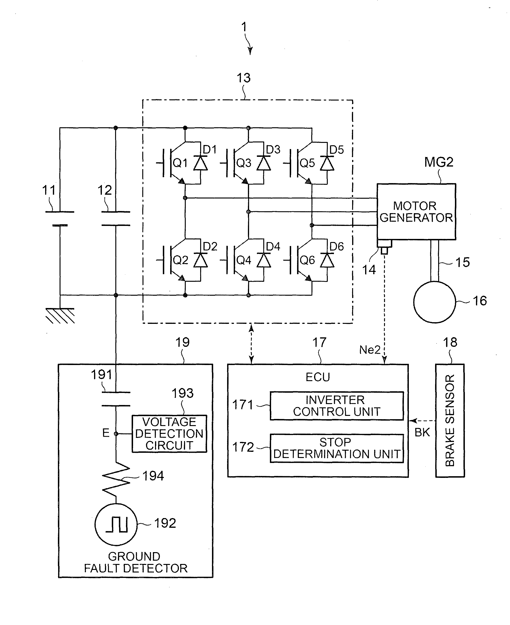
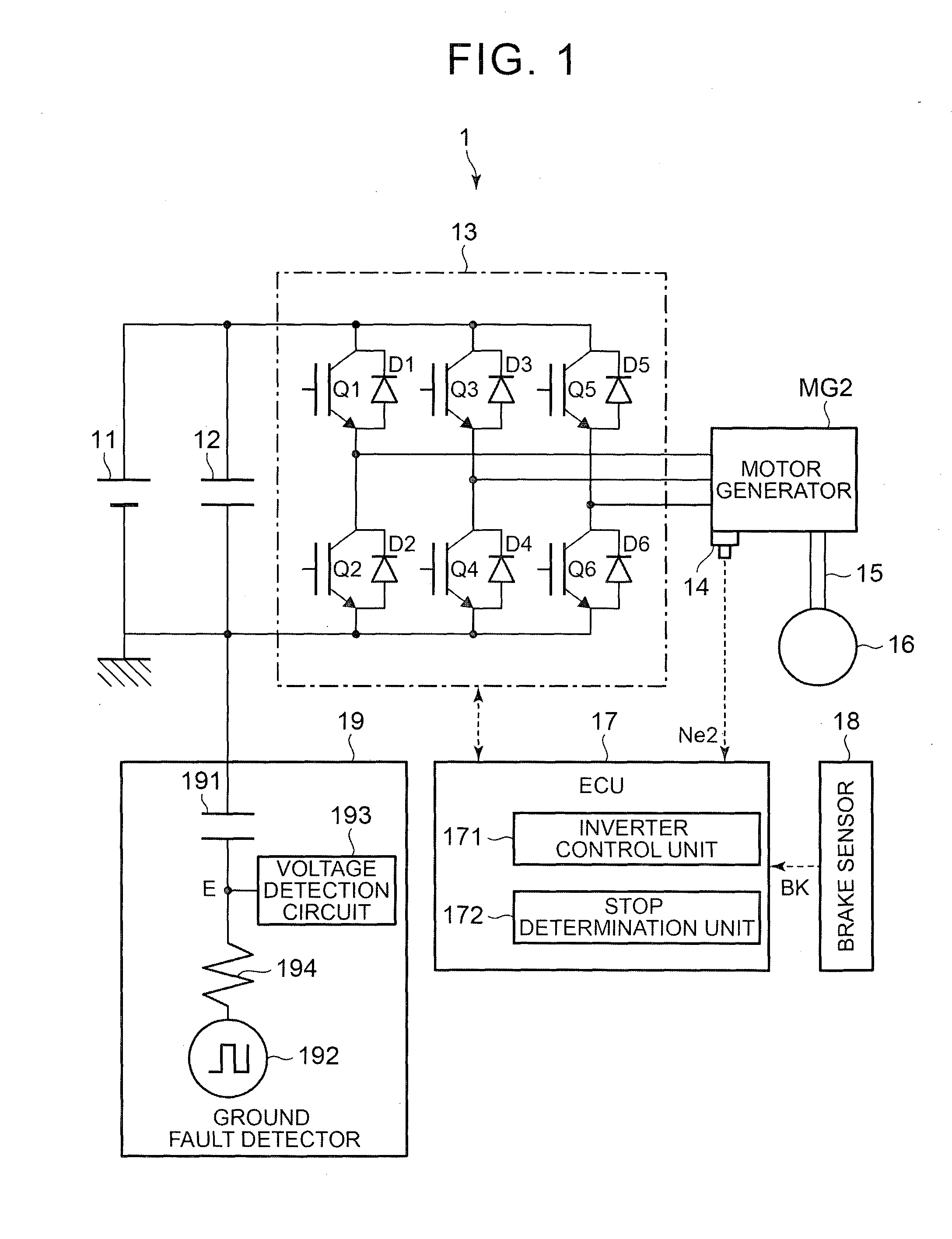
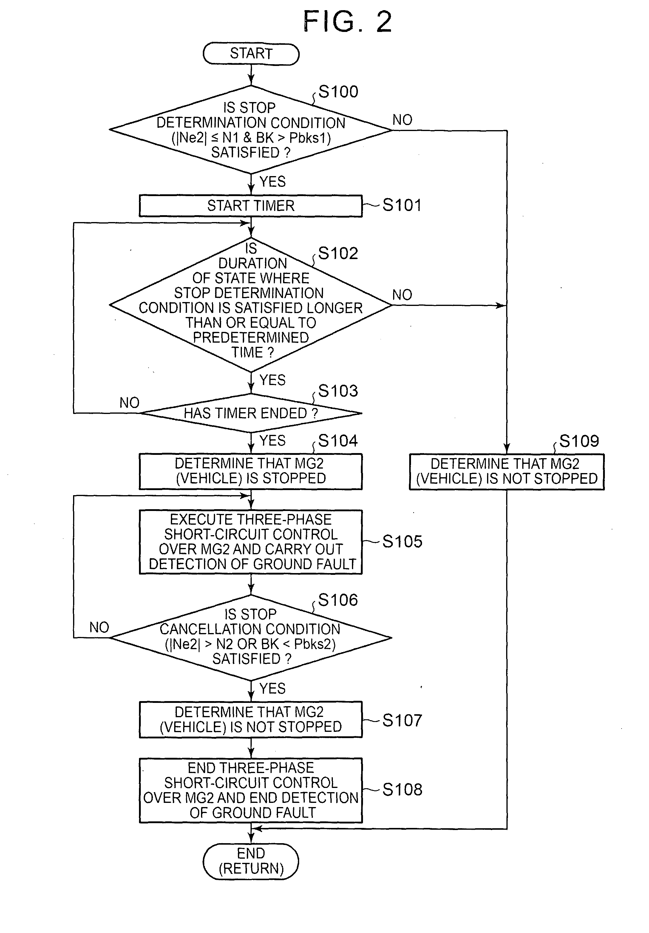
The vehicle control device described in this patent is able to accurately determine whether the vehicle is stopped or hunting (when the motor is rotating at a lower speed than usual). This is important because ground fault detectors can sometimes detect fluctuations in the electrical system due to hunting, and this can lead to incorrect detection of a ground fault. By accurately determining whether the vehicle is stopped, the control device can suppress frequent fluctuations in the determination and implement suitable detection of a ground fault. Overall, this results in a more reliable and accurate detection of ground faults and ensures safe operation of the vehicle.

Problems solved by technology

However, considering the accuracy of the rotation speed of the internal combustion engine, which is calculated from the output of the crank angle sensor, there arises a technical problem that it is difficult to highly accurately determine whether the vehicle is stopped on the basis of the rotation speed of the internal combustion engine.
For example, there arises a technical problem that it may be erroneously determined that the vehicle is stopped because of, for example, an accuracy error of the rotation speed of the internal combustion engine, which is calculated from the output of the crank angle sensor, although the vehicle is not stopped.
That is, the above-described technical problems can arise not only when the operation to determine whether the vehicle is stopped is carried out in association with the operation to carry out detection of a ground fault by using the technique described in JP 7-241002 A but also when the operation to determine whether the vehicle is stopped is carried out.

Method used


Image

  • Vehicle control device
  • Vehicle control device
  • Vehicle control device

Examples


second embodiment

(2-1) Configuration of Vehicle

[0116]Initially, the configuration of a vehicle 2 according to the second embodiment will be described with reference to FIG. 4. FIG. 4 is a block diagram that shows the configuration of the vehicle 2 according to the second embodiment.

[0117]As shown in FIG. 4, the vehicle 2 according to the second embodiment differs from the vehicle 1 according to the first embodiment in that the vehicle 2 further includes an engine ENG, a motor generator MG1, an inverter 13-1, a rotation angle sensor 14-1 and a power split mechanism 20. In addition, the vehicle 2 according to the second embodiment differs from the vehicle 1 according to the first embodiment in that the operation of the stop determination unit 172 is different. The other components of the vehicle 2 according to the second embodiment are the same as the other components of the vehicle 1 according to the first embodiment. However, for the sake of convenience of description, in the second embodiment, the ...


PUM


Abstract

A vehicle control device that controls a vehicle including a first electric motor that is driven at a rotation speed synchronized with a rotation speed of a drive shaft of the vehicle includes an electronic control unit. The electronic control unit is configured to carry out first determination that determines whether the rotation speed of the first electric motor is lower than or equal to a first threshold and whether a stop operation that stops the vehicle is being carried out, and to carry out second determination that the vehicle is stopped when the electronic control unit has determined in the first determination that the rotation speed of the first electric motor is lower than or equal to the first threshold and the stop operation is being carried out.

Description

BACKGROUND OF THE INVENTION[0001]1. Field of the Invention[0002]The invention relates to, for example, a technical field of a vehicle control device that controls a vehicle including an electric motor.[0003]2. Description of Related Art[0004]In recent years, a vehicle including an electric motor (a so-called motor) has become a focus of attention. As an example of such a vehicle including an electric motor, there is known a hybrid vehicle including both an electric motor and an internal combustion engine (see, for example, Japanese Patent Application Publication No. 2006-288051 (JP 2006-288051 A)). In addition, as such a vehicle including an electric motor, there is known an electric vehicle including an electric motor but not including an internal combustion engine (see, for example, Japanese Patent Application Publication No. 7-241002 (JP 7-241002 A)).[0005]JP 2006-288051 A describes a technique for, in the thus configured hybrid vehicle, executing three-phase short-circuit contro...

Claims


Application Information

Patent Timeline
IPC IPC(8): B60L3/12B60L3/00B60L15/20B60L50/15B60L50/16
CPCB60L3/12B60L3/0069B60L15/20B60L15/007B60L15/2009B60L2210/40B60L2240/12B60L2240/421B60L2240/423B60L2240/80B60L2250/26B60L50/40B60L50/61B60L50/16B60L58/20Y02T10/62Y02T10/64Y02T10/70Y02T10/72Y02T10/7072
Inventor NIIMI, YOSHITAKAOKAMURA, MASAKITSUJII, SHINTAROANG, WANLENGYAGUCHI, HIDEAKIMORISAKI, KEISUKE
Owner TOYOTA JIDOSHA KK
Why Eureka
Try Eureka