Image display device

a technology of image display and display device, which is applied in the field of image display device, can solve the problems of direct attachment of temperature sensor, low resolution, and inability to obtain clear images from monitoring objects, so as to improve the detection of machining error or abnormal abrasion of tools, improve the accuracy of determination, and suppress the effect of increasing maintenance costs

Active Publication Date: 2019-10-22
FANUC LTD
View PDF33 Cites 0 Cited by
  • Summary
  • Abstract
  • Description
  • Claims
  • Application Information

AI Technical Summary

Benefits of technology

[0014]According to the invention, even when a cutting fluid or chips are scattered inside the machining chamber of the machine tool, it is possible to display a clear image and a temperature distribution near a machining contact point between a tool and a workpiece or other portions. Further, it is possible to display a clear image and a temperature distribution of a main part of an industrial machine. Accordingly, when a temperature distribution (a temperature distribution based on machining) at an optimal machining state or an abnormal temperature distribution is visually checked by a human operator, it is possible to highly accurately determine whether the temperature distribution of the parts inside the machining chamber is normal or abnormal and thus to improve the machining error detection or the abnormal abrasion detection of the tool.
[0015]Further, since a clear image with a temperature distribution inside the machining chamber is displayed, there is no need to supply light into the machining chamber of the industrial machine or the machine tool and there is no need to install a device for supplying light into the machining chamber. Accordingly, an increase in maintenance cost can be suppressed. Further, since there is no need to supply light at all times for the long-time monitoring, an effect of saving energy can be expected.

Problems solved by technology

Here, there is a method of monitoring the temperature of the tool or the workpiece by using a temperature sensor, but since it is difficult to directly attach the temperature sensor depending on the tool or the workpiece in some cases, a thermography (a thermal image measurement device) is used as a non-contact temperature sensor.
Incidentally, since the thermography measures infrared rays emitted from an object, a problem arises in that a resolution is lower than that of a visible image obtained by a general camera and a clear image cannot be obtained from a monitoring object.
However, in the technology disclosed in Japanese Patent Application Laid-Open No. 09-273964 described above, since the temperature of the tool is not actually measured, it is not possible to calculate a correct temperature distribution when abnormality occurs in the tool such that heat is generated by the abnormal abrasion of the tool.
That is, a problem arises in that an abnormal increase in temperature of the tool during the machining of the workpiece cannot be detected.
Further, the technology disclosed in Japanese Patent Application Laid-Open No. 2010-181324 described above is not originally dedicated for machine tools or industrial machines and an influence of a cutting fluid or the like sprayed to the tool or the workpiece during machining is not considered.
For that reason, when this technology is used to monitor the tool or the workpiece, a problem arises in that the tool 3 or the workpiece 4 cannot be clearly displayed since a scattering cutting fluid or chips are included in the image of the camera photographing the tool 3 or the workpiece 4 during machining as illustrated in FIGS. 9A and 9B.
As a result, another problem arises in that cost increases.

Method used


Image

  • Image display device
  • Image display device
  • Image display device

Examples


Embodiment Construction

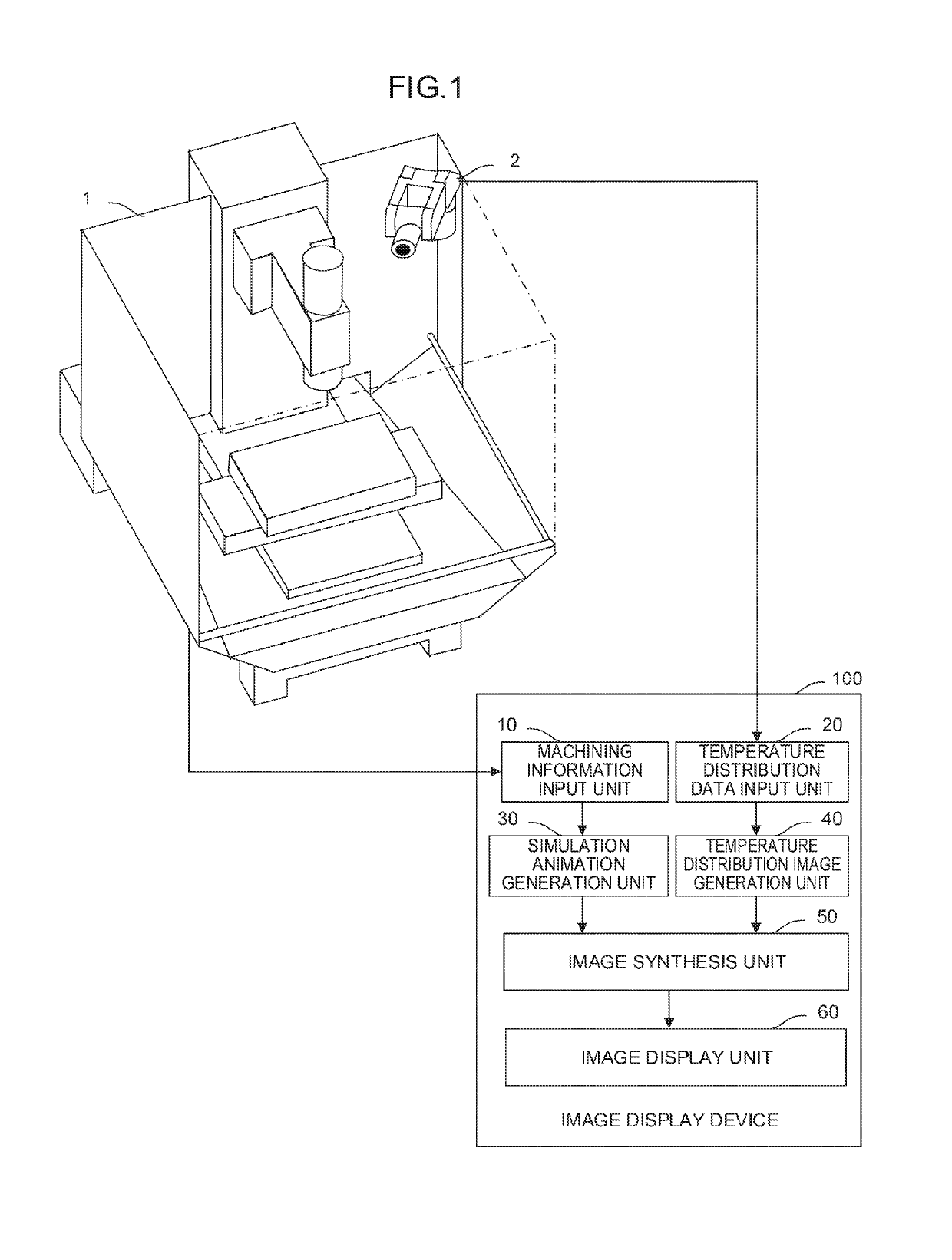
[0025]FIG. 1 is a schematic functional block diagram of an image display device according to an embodiment of the invention.

[0026]An image display device 100 of the embodiment displays a temperature distribution in a machining chamber including the vicinity of a machining contact point between a tool and a workpiece when the workpiece is machined by a machine tool 1 including a thermography 2. The image display device 100 includes a machining information input unit 10, a temperature distribution data input unit 20, a simulation animation generation unit 30, a temperature distribution image generation unit 40, an image synthesis unit 50, and an image display unit 60.

[0027]The machining information input unit 10 is connected to a control unit (not illustrated) of the machine tool 1 and acquires machining information representing a machining status of the machine tool 1. The machining information input unit 10 acquires information necessary for a three-dimensional simulation performed ...


PUM


Abstract

An image display device acquires data representing a status of a temperature distribution of a machining machine based on information on machining and generates a temperature distribution image from the acquired data. Further, a three-dimensional machining simulation representing a status of machining is performed to generate a three-dimensional simulation animation and a projection image is generated from the three-dimensional simulation animation. Then, an image obtained by synthesizing the temperature distribution image and the projection image is generated and displayed.

Description

CROSS-REFERENCE TO RELATED APPLICATIONS[0001]This application is a new U.S. Patent Application that claims benefit of Japanese Patent Application No. 2016-248164, filed Dec. 21, 2016, the disclosure of this application is being incorporated herein by reference in its entirety for all purposes.BACKGROUND OF THE INVENTION1. Field of the Invention[0002]The present invention relates to an image display device and particularly to an image display device for superimposing and displaying a clear image of a tool or a workpiece and a temperature distribution image.2. Description of the Related Art[0003]In a machine tool or an industrial machine, there is a need to monitor a temperature of a tool or a workpiece during machining in order to prevent abnormal abrasion or damage of the tool or ensure uniform machining quality. At this time, in order to more accurately determine whether a temperature distribution is normal or abnormal, it is more important to acquire a temperature distribution hav...

Claims


Application Information

Patent Timeline
Patent Type & Authority Patents(United States)
IPC IPC(8): G01J5/02G06T7/00G06T13/20G06T15/50G01J5/48G01J5/00
CPCG06T7/0002G01J5/027G01J5/025G06T13/20G06T15/503G01J5/48G01J2005/0085G06T2219/008G06T2207/10048G06T2215/16G01J2005/0077G01J5/0066H04N5/265G01J5/485
Inventor HIRAMATSU, AKIO
Owner FANUC LTD
Why Eureka
Try Eureka