Controlling method of robot system, program, recording medium, and robot system

a robot system and control method technology, applied in the field of robot systems, can solve the problems of reducing movement accuracy, requiring a skilled technician to take a long time, and unable to highly accurately detect the origin offset of the respective joints, so as to achieve the effect of accurately determining the presence or absence of an origin offs

Active Publication Date: 2017-03-07
CANON KK
View PDF11 Cites 0 Cited by
  • Summary
  • Abstract
  • Description
  • Claims
  • Application Information

AI Technical Summary

Benefits of technology

[0011]The present invention has an object to provide a controlling method of a robot system that can highly accurately determine presence or absence of an origin offset at each of individual joints even with a small number of cameras.

Problems solved by technology

The multi joint robot may interfere with another object during installation, teaching or actual movement to cause an overload on a certain joint; the joint, in turn, causes an origin offset (rotational axis offset) at the joint.
Actual movement in a state where the certain joint has the origin offset may possibly reduce movement accuracy, cause a jig or a workpiece to fall off, and cause an interference with another object that results in an overload.
Evaluation of the origin offsets of many joints of the multi joint robot thus requires a skilled technician to take a long time.
However, measurement of the origin offsets of multiple joints through one camera cannot highly accurately detect the origin offsets of the respective joints.
However, installation of many cameras around the multi joint robot having a high degree of freedom is economically unfavorable.
Furthermore, it is difficult to prepare positions where the cameras are to be installed.

Method used


Image

  • Controlling method of robot system, program, recording medium, and robot system
  • Controlling method of robot system, program, recording medium, and robot system
  • Controlling method of robot system, program, recording medium, and robot system

Examples


embodiment 1

Multi Joint Robot

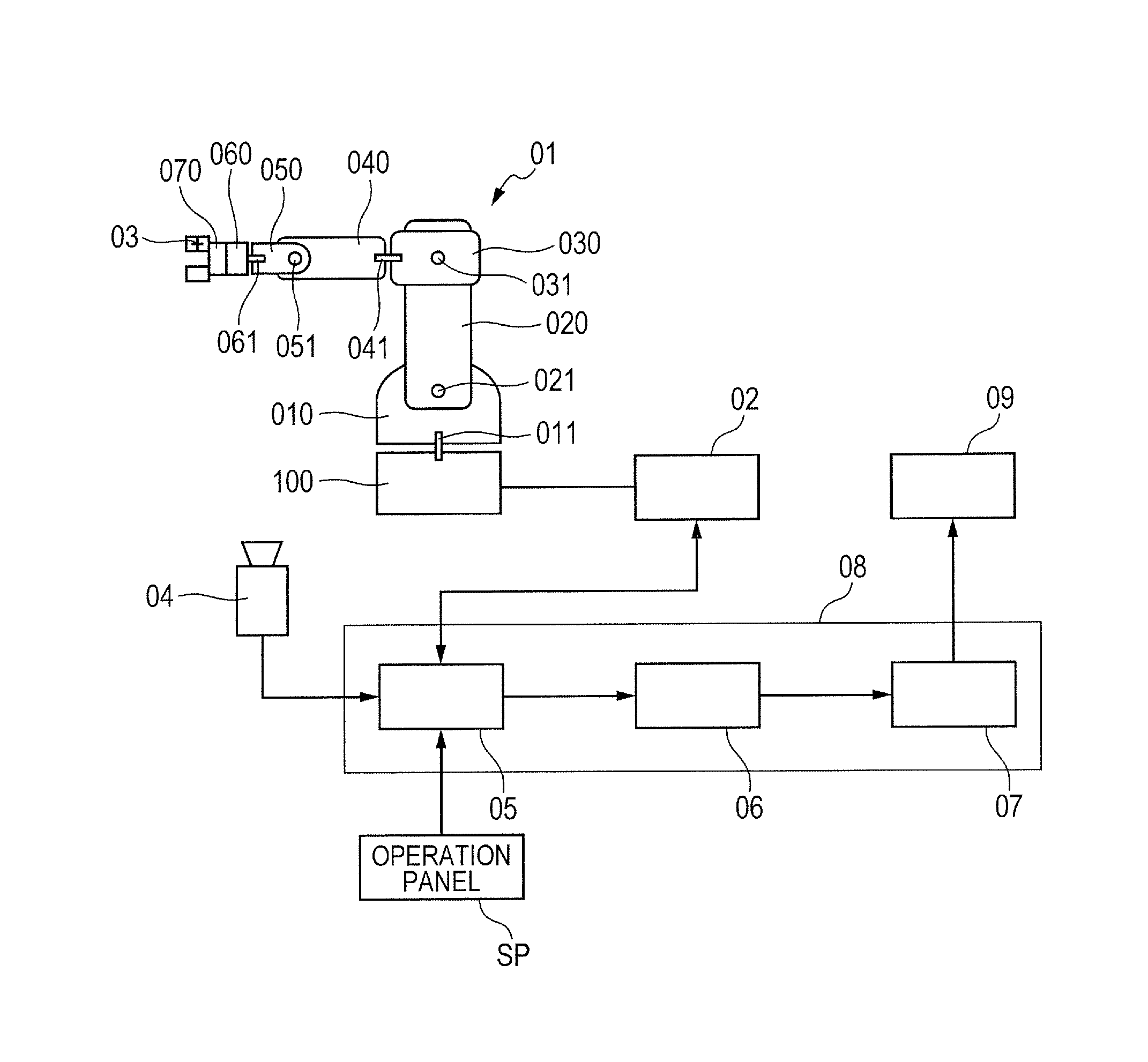
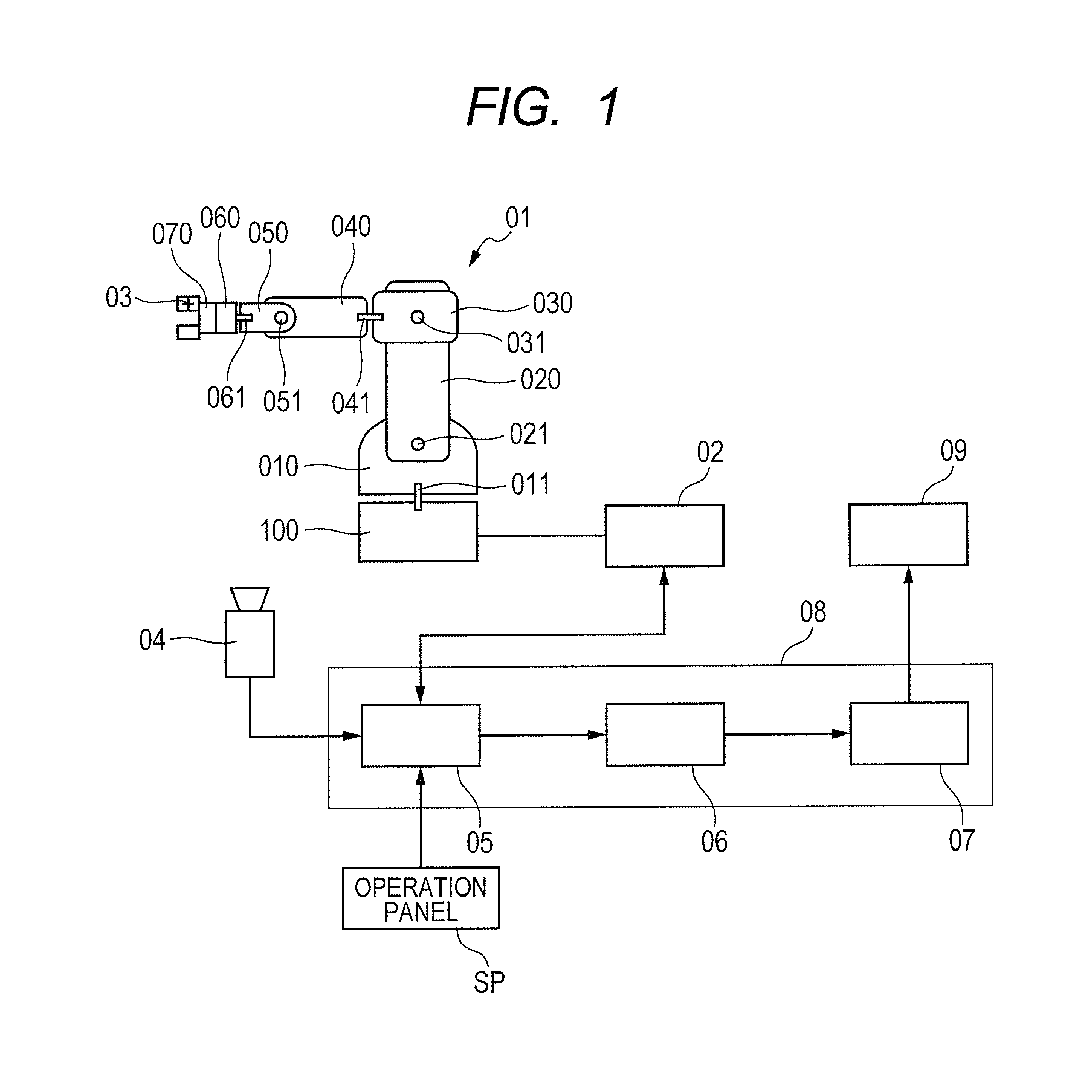
[0022]FIG. 1 is a diagram illustrating an overall configuration of a robot inspecting system of Embodiment 1. As illustrated in FIG. 1, a robot system includes: a robot 01, which is an example of a multi joint robot; and a camera 04, which is an example of a camera. A computer of a controlling unit 08, which is an example of a controlling unit, executes a program to control this system. The program is recorded in a recording medium, such as an optical disk, and then provided.

[0023]The robot 01 is a six-axis multi joint robot that includes an end effector 070 on a link 060 at a front end. A base 100 and a link 010 of the robot 01 are coupled to each other by a torsional joint 011 that rotates around a rotational axis in the Z-axis direction. The torsional joint 011 has a movable range of ±180 degrees from an initial position and orientation.

[0024]The link 010 and a link 020 of the robot 01 are coupled to each other by a pivotal joint 021 that rotates around a rotatio...


PUM


Abstract

A controlling method of a robot system is provided with highly accurately determination of an origin offset at individual joints, even with a small number of cameras. A controlling unit 08 controls a robot 01 and a camera 04 to perform a photographing step for each of pivotal joints 021, 031 and 051 to acquire photographed data, and subsequently performs computational control. The photographing step assigns predetermined coordinate angles to multiple joints of the robot 01, respectively, to cause the joints to take predetermined positions and orientations, and subsequently causes the camera 04 to photograph a mark 03 during a process of causing the robot 01 to rotate at one of the multiple joints from the predetermined position and orientation. The computational control identifies the joint causing a rotational axis offset among the multiple joints of the robot 01, based on the photographed data acquired by trajectory acquiring control.

Description

BACKGROUND OF THE INVENTION[0001]Field of the Invention[0002]The present invention relates to a robot system including a multi joint robot and a camera. More specifically, the present invention relates to a method of determining a rotational axis offset of multiple joints of a multi joint robot.[0003]Description of the Related Art[0004]Multi joint robots in which both ends of link units are coupled by pivotal joints to allow the link units to bend have been widely used. The multi joint robots typically include torsional joints that allow some of link units to rotate in cross sections perpendicular to the longitudinal directions of the link units in torsional directions. Accordingly, the multi joint robots can perform complicated movement, such as six-axis motion or seven-axis motion, which is similar to the movement of human arms.[0005]The multi joint robot may interfere with another object during installation, teaching or actual movement to cause an overload on a certain joint; the...

Claims


Application Information

Patent Timeline
Patent Type & Authority Patents(United States)
IPC IPC(8): B25J9/16B25J19/02
CPCB25J9/1692B25J19/021G05B2219/39039G05B2219/39391Y10S901/09
Inventor OGAWARA, TAKAYUKI
Owner CANON KK
Why Eureka
Try Eureka