
Light guiding plate, optical films, backlight module, array substrate and liquid crystal module

Inactive Publication Date: 2016-06-16
BOE TECH GRP CO LTD
View PDF9 Cites 5 Cited by
  • Summary
  • Abstract
  • Description
  • Claims
  • Application Information

AI Technical Summary

Benefits of technology

The patent provides a new design for a backlight module used in TFT-LCD displays. The design includes a light guiding plate, optical film, and a reflective layer with multiple holes that act as a point light source. The lights from these sources are then collimated by a light collimating layer, resulting in a more uniform and bright light. This design prevents light leakage and ensures consistent brightness across the display from different viewing angles. Overall, the technology improves the collimation of the backlight and reduces viewing angle dependency in TFT-LCD displays.

Problems solved by technology

An image is displayed by using the optical property of the liquid crystal molecules, but such optical property may narrow a viewing angle of the liquid crystal display.
Since the viewing angle property of the liquid crystal is not uniform, the gray-level inversion or color offset becomes serious at the viewing angles other than a normal direction of the display panel.
However, the above two methods can not solve the viewing angle problem of TFT-LCD.

Method used


Image

  • Light guiding plate, optical films, backlight module, array substrate and liquid crystal module
  • Light guiding plate, optical films, backlight module, array substrate and liquid crystal module
  • Light guiding plate, optical films, backlight module, array substrate and liquid crystal module

Examples


first embodiment

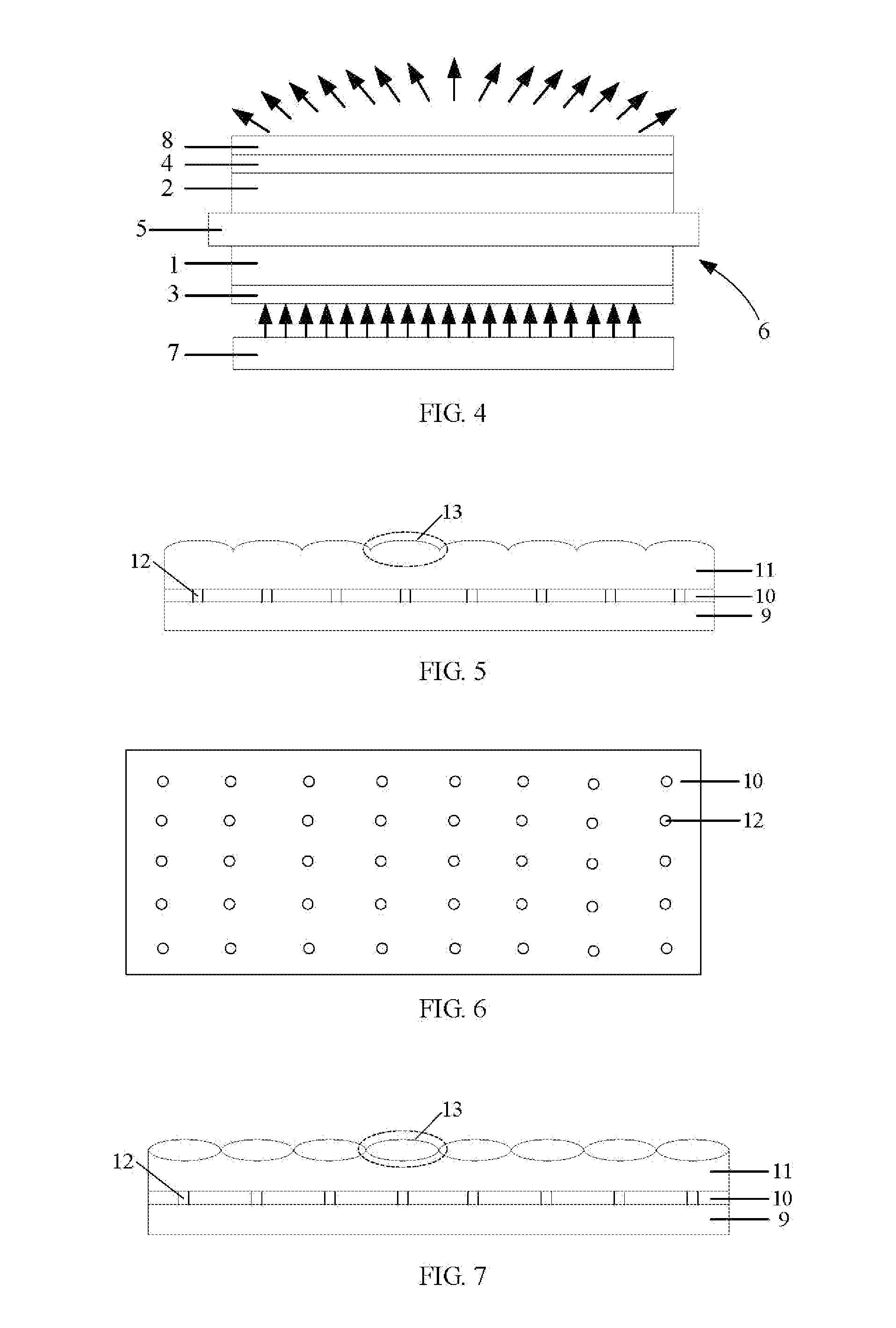
[0027]As shown in FIGS. 5-7, in order to make the lights incident at the same angle into the array substrate, a light guiding plate 9 is provided in the present embodiment. A reflective layer 10 and a light collimating layer 11 are formed on the light guiding plate 9 by a coating, depositing, sputtering process, etc. The reflective layer 10 is positioned below the light collimating layer 11, and the reflective layer 10 is formed with a plurality of holes 12, so as to form a point light source in each hole 12. The lights from each point light source is collimated by the light collimating layer 11, so that the emitted lights propagate in the same direction, as shown in FIG. 8. In general, the lights are vertically emitted from a surface of the light guiding plate 9.

[0028]There are various optical structures which serve to emit parallel light from the point light sources, for example, the optical structure could be a convex lens structure. For example, the light collimating layer 11 ma...

second embodiment

[0030]In order to make the light incident into an array substrate at the same angle, an optical film is provided between a light guiding plate and the array substrate in the present embodiment. The optical film comprises a reflective layer and a light collimating layer, and the reflective layer is positioned below the light collimating layer, and the reflective layer is formed with a plurality of holes. Also, the light collimating layer may be designed to have a plurality of micro lens structures. The micro lens structures and the holes in the reflective layer have a one to one correspondence, and each hole are located at a focus point of the corresponding micro lens structure, so that the lights are emitted in parallel from the light collimating layer, and then is incident to the array substrate at the same angle.

third embodiment

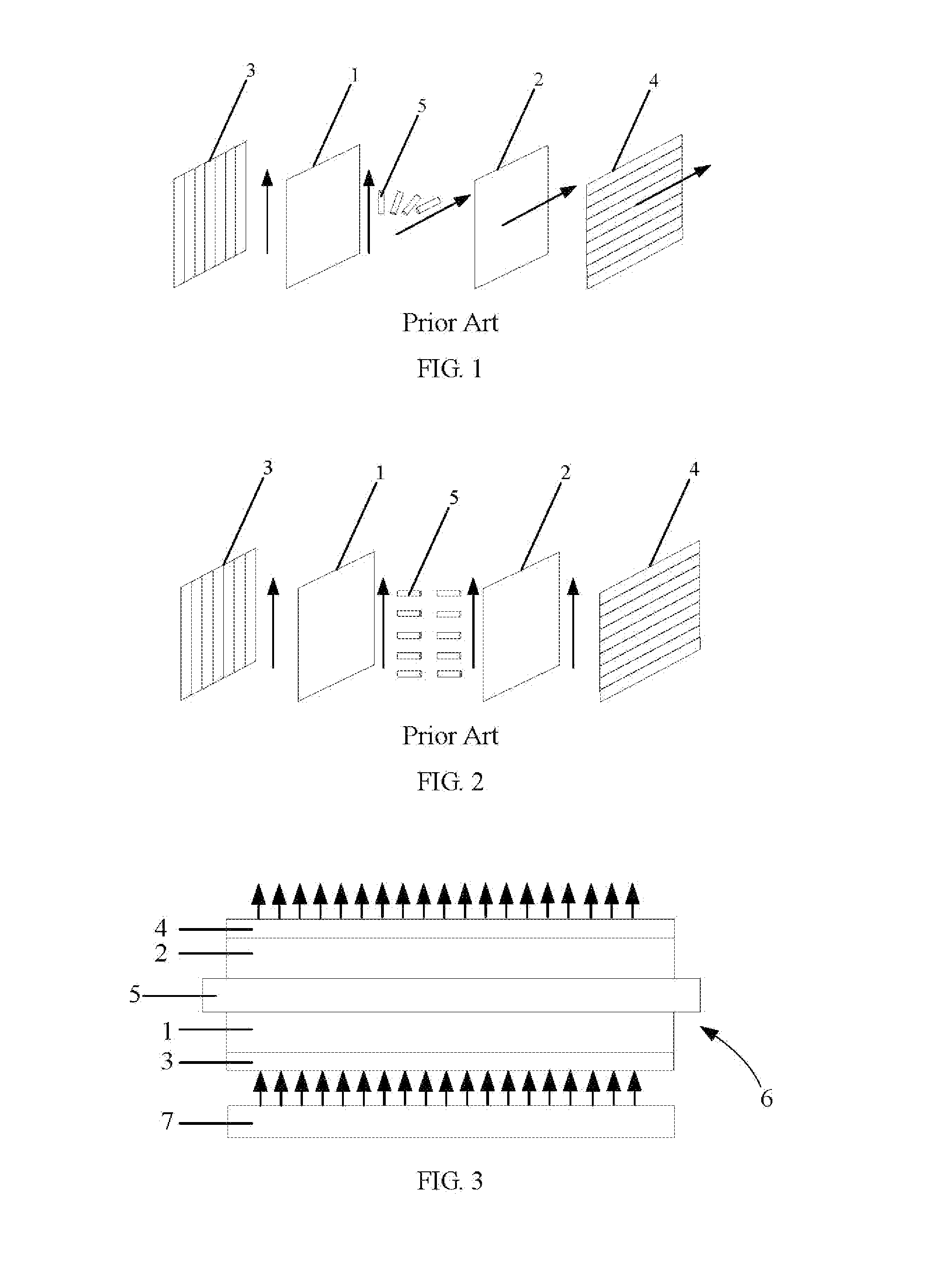
[0031]A liquid crystal module is provided in the present embodiment. The liquid crystal module comprises a light guiding plate and an optical film on the light guiding plate. The light guiding plate can be the light guiding plate according to the first embodiment, or the optical film can be the optical film according to the second embodiment, so that the lights are incident perpendicular into the array substrate 1 at the same angle, and thus the light leakage caused by different viewing angles can be prevented. Since the lights viewed from other angles by the users is obtained by diffusing the lights having the same incident angle at a surface of the display panel, the same brightness may be maintained when viewed from different angles by the users, and the problem of the viewing angle dependency in the TFT-LCD can be overcome.


PUM


Abstract

The embodiments of the present invention provide a light guiding plate, an optical film, a backlight module, an array substrate and a liquid crystal module. A reflective layer and a light collimating layer are formed on one surface of the light guiding plate, the reflective layer is positioned below the light collimating layer and has a plurality of holes. The light from the point light source is collimated by the light collimating layer) to form a parallel lights, so that the lights are incident into the array substrate at the same angle without any lights at other angles. Thus, the same brightness is maintained when viewed from different angles by the users, and the problem of the viewing angle dependency in the TFT-LCD is overcome.

Description

FIELD[0001]Embodiments of present invention relate to a display technology field, more particularly, to a light guiding plate, an optical film, a backlight module, an array substrate and a liquid crystal module.BACKGROUND[0002]Thin Film Transistor-Liquid Crystal Display (TFT-LCD) has advantages of small volume, low power consumption, no radiation, etc., so it becomes a dominant product in current flat panel display market. As shown in FIG. 1, the TFT-LCD has a main structure of liquid crystal module which includes an array substrate 1 and a color filter substrate 2 assembled as a cell, and polarized plates 3 and 4 with polarization directions perpendicular to each other disposed on outer sides of the array substrate 1 and the color filter substrate 2 respectively. A displaying principle of the TFT-LCD is described as following. Lights pass through the polarized plate 3 on the outer side of array substrate 1 to form a polarized light. With the TFTs as switching elements, a driving el...

Claims


Application Information

Patent Timeline
IPC IPC(8): G02F1/1335
CPCG02F1/133606G02F1/133524G02F2001/133607G02F1/133603G02F1/133605G02F1/133611G02B6/0055G02F1/133607
Inventor QIN, GUANGKUI
Owner BOE TECH GRP CO LTD
Learn More