
Method and device for linear connection and separation of two elements, with offset energy means

a technology of offset energy and connection and separation, applied in the direction of cosmonautic components, fireworks, weapons, etc., can solve the problems of high failure risk, significant impact on the structure, and damage to payloads

Active Publication Date: 2016-06-16
ARIANEGRP SAS
View PDF7 Cites 7 Cited by
  • Summary
  • Abstract
  • Description
  • Claims
  • Application Information

AI Technical Summary

Benefits of technology

The invention describes a method for securely connecting and separating two elements by a local connection that has to be made quickly and at a distance from the connection. This method involves connecting the two elements at two corresponding surfaces, one of which is a separating wall. The separating wall has thermite, which can be remotely triggered to cause a quick warming-up that results in the separation of the two elements, without causing any damage to the connection means. The invention also describes a device for implementing this method and an aeronautic launcher that includes the method for securely connecting and separating elements. The technical effects of the invention include quick and safe separation of connected elements, minimizing damage to the connection means, and enabling secure and reliable separation of elements in an aeronautic launcher.

Problems solved by technology

1) the connections by bolting, riveting and pyrotechnic cutting off by pressure and local temperature rise of the structure. These systems, due to their operation, generate ejected material debris. Moreover, the cutting off causes a significant impact in the structure, which may be damageable for the payloads of the launcher;
This type of solution generates much less impact than the two previous ones, but requires several bolts to transmit strains from one element to the other, thus generating higher failure risks because of the number of devices involved;
This type of solution does not enable high strains to be transmitted between both elements and does not allow for too large of diameters for the launchers.
Also in this case, the stress relief causes a high impact in the structures.

Method used


Image

  • Method and device for linear connection and separation of two elements, with offset energy means
  • Method and device for linear connection and separation of two elements, with offset energy means
  • Method and device for linear connection and separation of two elements, with offset energy means

Examples


Embodiment Construction

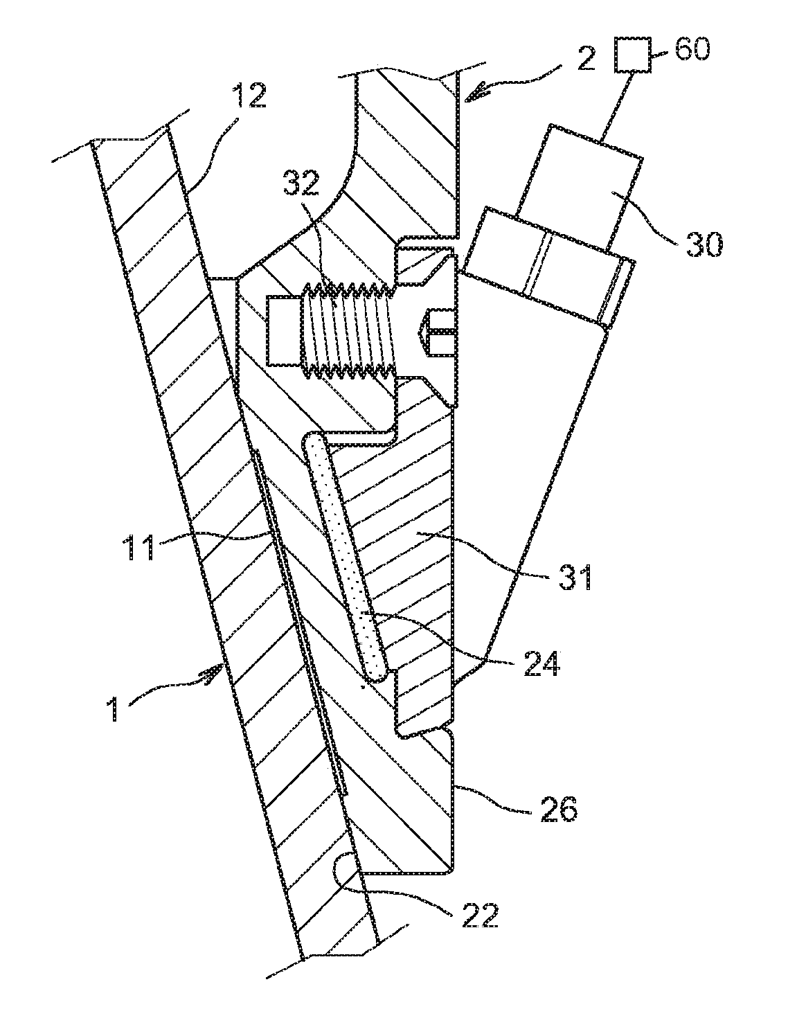
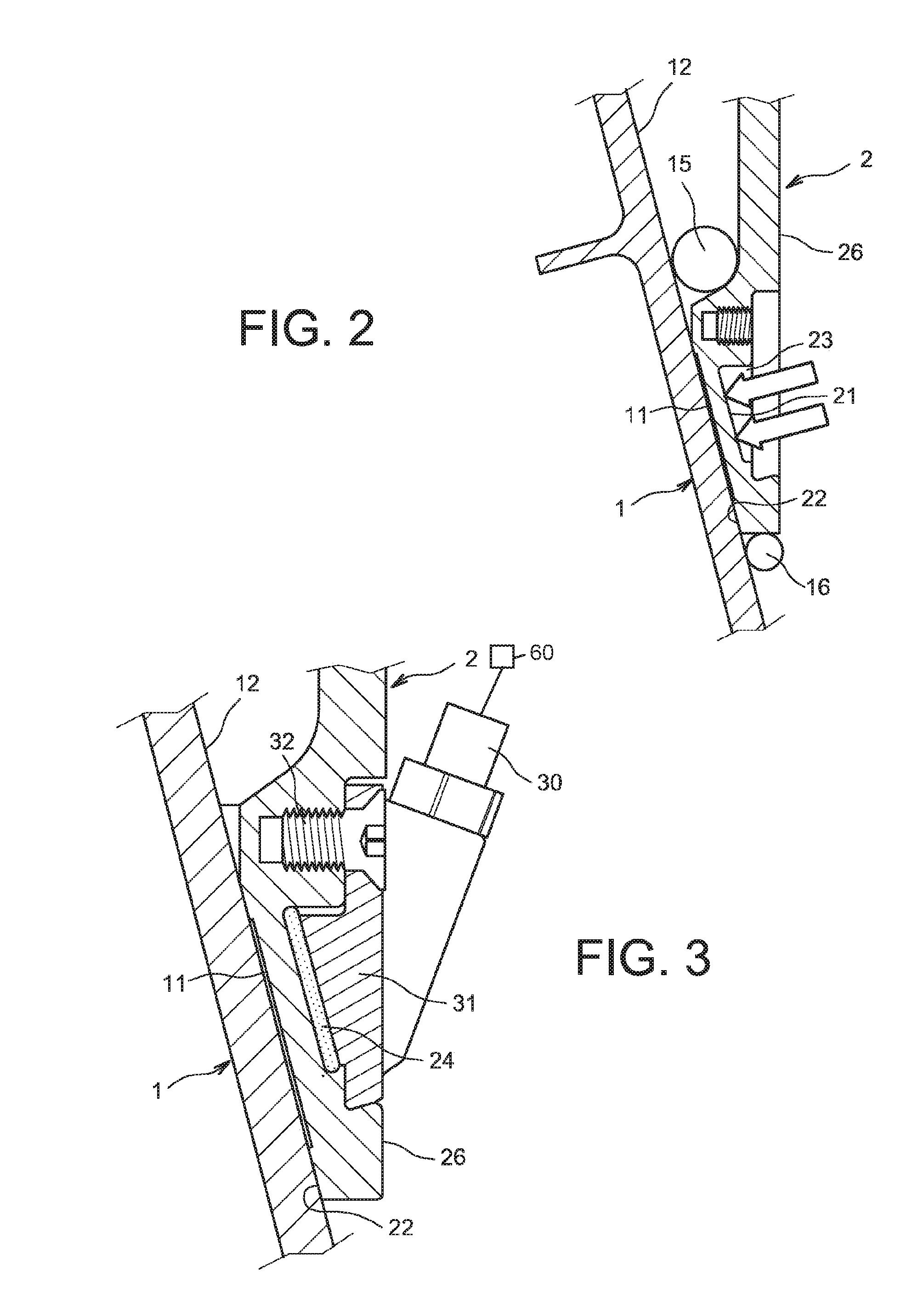
[0033]FIG. 2 shows a scheme of the method and the device according to the invention, applied to two elements 1 and 2, which are, in the preferential application of the invention, for the first element 1, an aerospace or aeronautic launcher with the rank n, for example the first stage of a launcher on the end of which is attached the second element, which is either a second launcher with a rank n+1, that is preferably a second launcher stage, or an operational load, for example containing equipment or a facility to be put into orbit. The front end of the first element 1 is conical, that is the outer wall 12 of this first element 1 is conical to facilitate the separation thereof, this conicity being optional. Correspondingly, the back end of the second element 2 has an inner wall 22, which is conical, with the same conicity as the outer wall 12 of the first launcher. 1. The interface between both these surfaces, the outer surface 12 of the first launcher 1 and the inner surface 22 of ...


PUM


Abstract

A method and device enable the linear separation of two elements attached to each other through two connecting surfaces which are conical in this example, of a first element and a second element respectively, using thermite placed on the other side of the wall of the outer element, facing a connecting arrangement placed between both connecting surfaces. An electrical triggering of the thermite causes a quick and local warming-up, at the connecting arrangement which, after melting, enables both elements to be separated.

Description

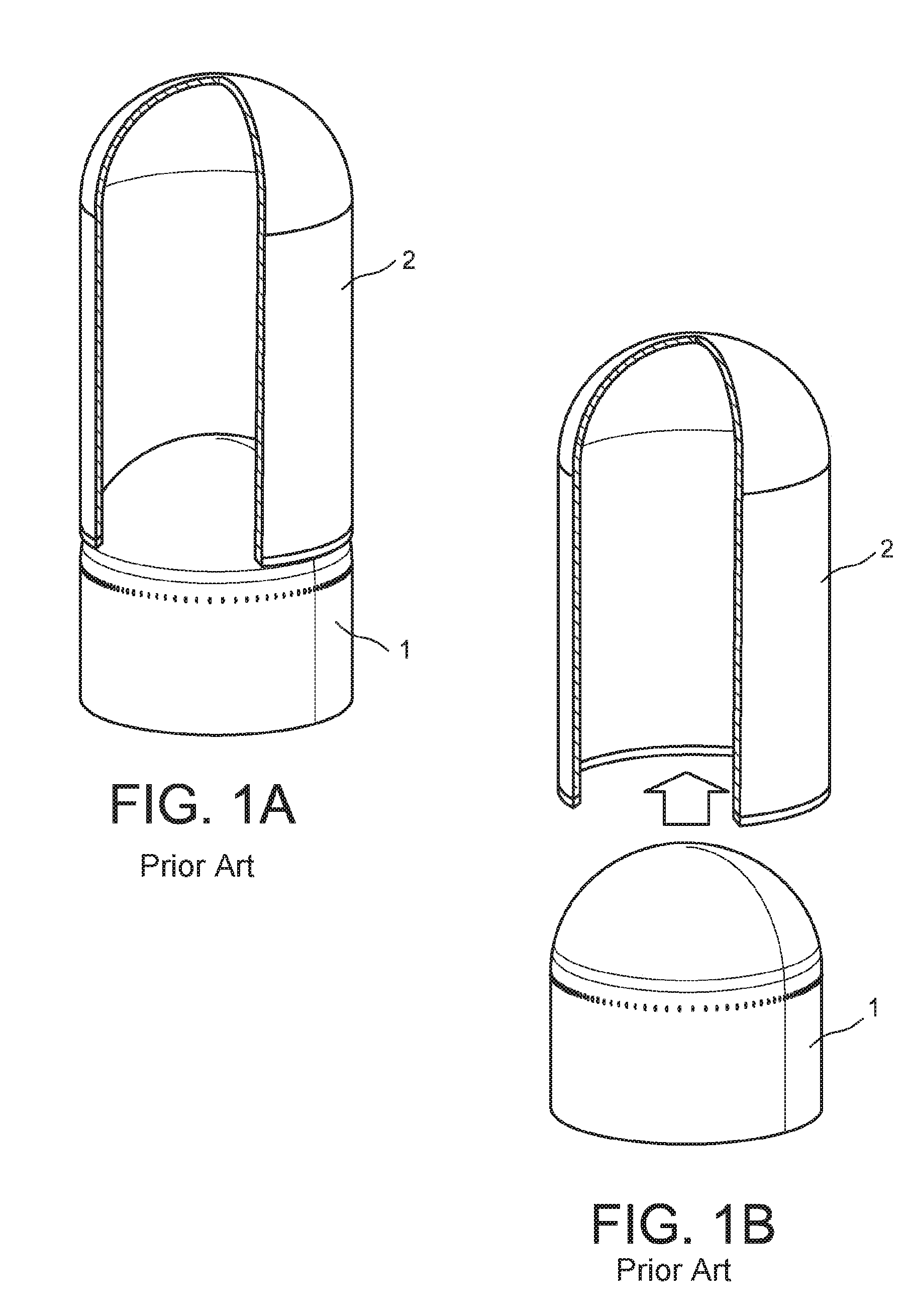
CROSS-REFERENCES TO RELATED APPLICATIONS[0001]This application claims the benefit of the French patent application No. 1357637 filed on Aug. 1, 2013, the entire disclosures of which are incorporated herein by way of reference.BACKGROUND OF THE INVENTION[0002]The invention relates to a linear separation, as smooth as possible, of a first element with respect to a second element, which are rigidly connected beforehand The invention is preferably applicable to spatial launchers, for separating stages from each other, of a launcher and of its cap or a stage and the payload, of missiles, space probes, or even planes, in the case of a payload release. The purpose of this separation is to reduce the weight of the on-board assembly, or to release a payload. These applications are characterized in that there is a need for separating objects that may be fragile, for example a satellite, and the connection of which has had to undergo high mechanical loads, as those undergone when propelled by ...

Claims


Application Information

Patent Timeline
Patent Type & Authority Applications(United States)
IPC IPC(8): F42B15/36
CPCF42B15/36B64G1/641F42B15/38B64G1/6455B64G1/645
Inventor COMTESSE, PATRICKMEDINA, FELIPEPREAUD, LUC
Owner ARIANEGRP SAS
Learn More