
Sensor device with mounting means

Active Publication Date: 2016-06-09
AB SKF
View PDF5 Cites 8 Cited by
  • Summary
  • Abstract
  • Description
  • Claims
  • Application Information

AI Technical Summary

Benefits of technology

The patent proposes the use of a zinc alloy as a mounting element for transmitting signals, specifically acoustic emissions. This alloy has been found to provide good signal transmission and can be easily manufactured using die casting, a process commonly used for structural connectors. The patent also suggests the use of a signal processing device that is protected from vibration, temperature, fire, and other environmental factors. Overall, the patent aims to provide a solution for transmitting signals in a reliable and efficient way.

Problems solved by technology

It is frequently the case that it is impractical to install sensor elements directly on individual components of interest.

Method used


Image

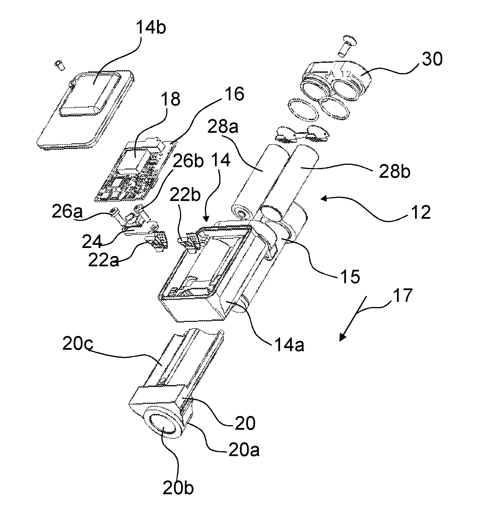
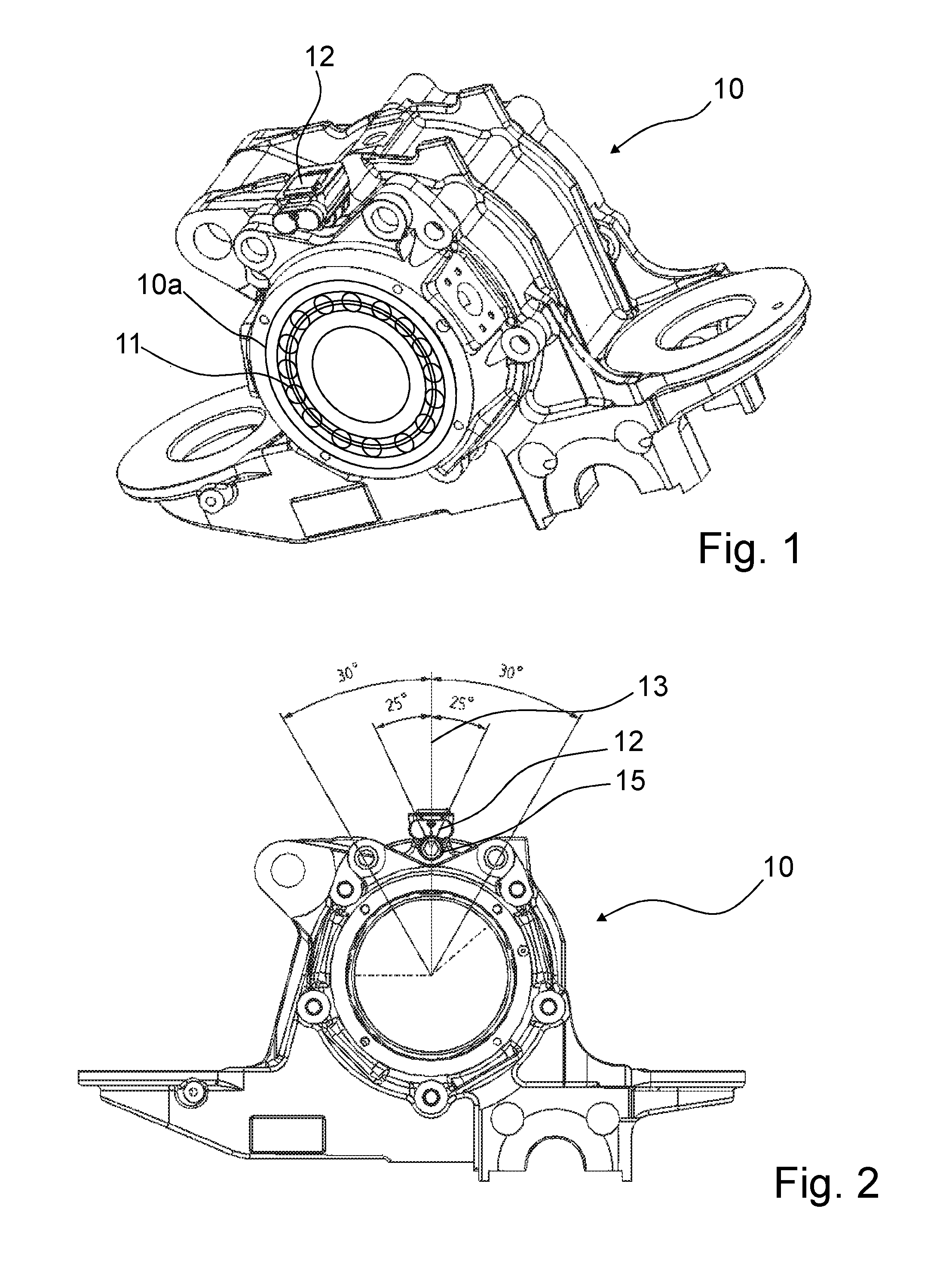
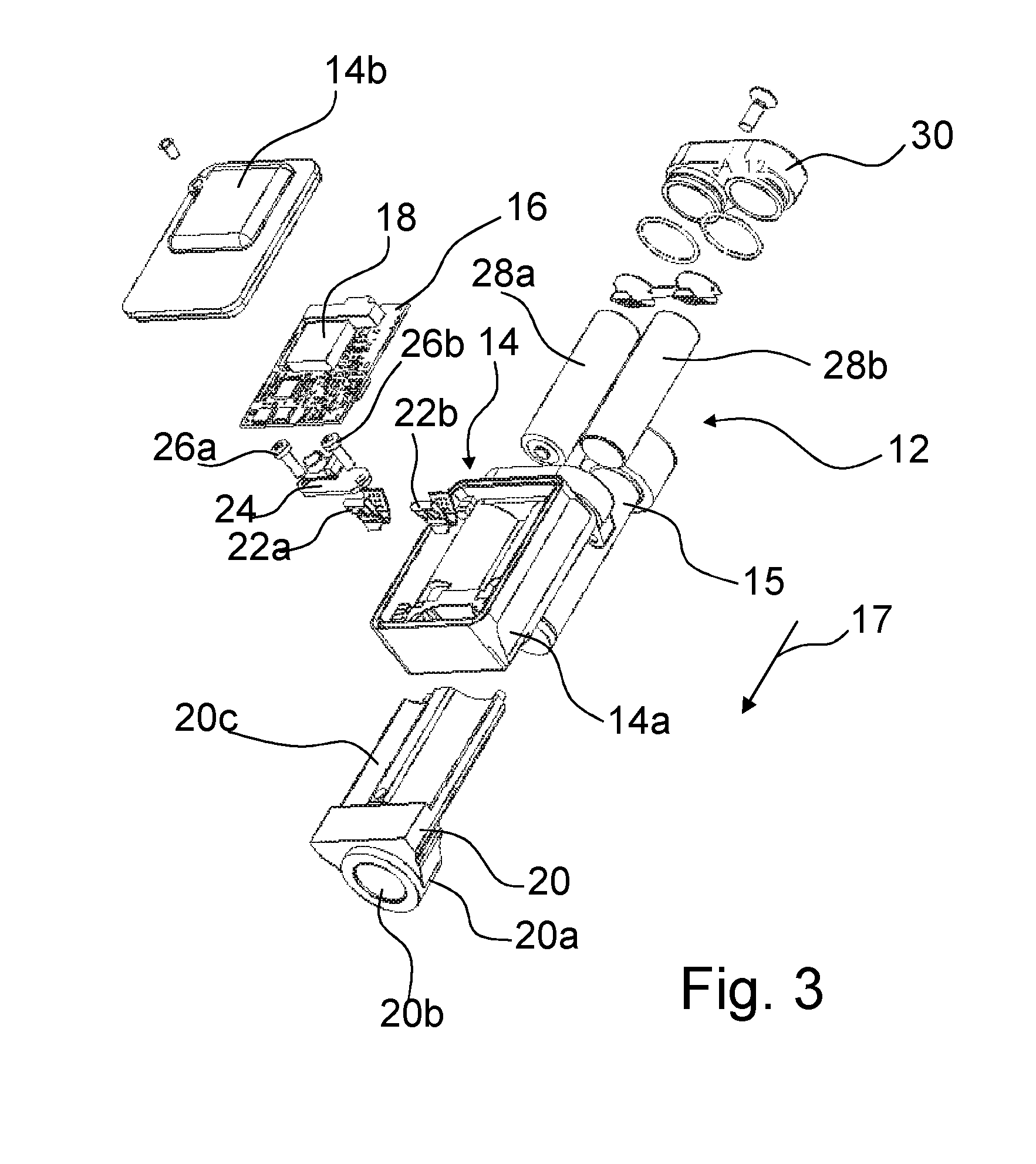
  • Sensor device with mounting means
  • Sensor device with mounting means
  • Sensor device with mounting means

Examples


sixth embodiment

[0069]FIGS. 11 to 14 are views of a sensor device according to the invention. Instead of using batteries witch clips a battery pack 28c with a connector 28d is used. The battery pack 28c is arranged in a space provided between a PCB as the signal processing device 16 and a body part as the second portion 20c of the bracket 20. The battery cover 30 is fixed by two screws 30a, 30b and kept assembled to a housing 14 of the device by a cable tie 30c.

[0070]Further embodiments of the invention include spacers to be arranged between the bracket 20 and the axlebox 10.

seventh embodiment

[0071]FIG. 15 is a sensor device according to the invention. The mounting element 20 is formed as a sled having a ground plate portion 20a configured to hold the sensors 22a, 22b and rods protruding from the ground plate portion as means for holding two coil springs 32a, 32b for pressing the ground plate portion to the component of interest.

[0072]The embodiment with a spring loaded sled with piezoelectric sensor elements and temperature sensor mounted allows sensor modules to be affixed and detached from a monitoring site with relative ease. When using this sled approach, it is essential that good signal energy transmission to the piezoelectric crystals is achieved. An important aspect to this is the surface of the sled being in contact with the component being monitored is required to be flat and smooth. When stainless steel is used and formed using a bending process, the contact surface becomes arched which results in poor AE transmission across the interface.

[0073]FIG. 16 is a mo...


PUM

PropertyMeasurementUnit
Fractionaaaaaaaaaa
Fractionaaaaaaaaaa
Percent by massaaaaaaaaaa

Abstract

A sensor device for monitoring a component of interest, including at least one sensor for measuring at least one parameter indicative of condition of the component of interest, signal processing device for processing the signals of the sensor, and a mounting element for mounting the sensor device close to the component of interest. The mounting element can be made of a zinc alloy.

Description

CROSS REFERENCE TO RELATED APPLICATION[0001]This is a Non-Provisional patent application, filed under the Paris Convention, claiming the benefit of:[0002]Great Britain (GB) Patent Application Number 1421781.4, filed on 8 Dec. 2014 (Aug. 12, 2014), and[0003]Great Britain (GB) Patent Application Number 1421781.4, filed on 3 Mar. 2015 (Mar. 3, 2015), which are incorporated herein by reference in their entireties.FIELD OF THE INVENTION[0004]The invention relates to a sensor device for monitoring a mechanical component of interest, in particular a train bearing arranged in a train axle box.BACKGROUND OF THE INVENTION[0005]The invention relates to devices for monitoring the condition of components, in particular of rotating components of vehicles or machinery. When attempting to monitor the condition, it is often difficult to find suitable locations for the required sensor systems such that they can be applied without disassembly of mechanical systems and resultant destruction of the asse...

Claims


Application Information

Patent Timeline
IPC IPC(8): G01D11/24B61L15/00
CPCB61L15/0081G01D11/245G01M13/04G01M13/045G01D5/00G01D11/00B61F15/20F16C19/522G01D11/02G01D11/30G01K1/16G01H1/003G01H3/00F16C2326/10F16C19/525F16C19/527F16C41/00F16C2233/00F16C2204/50F16C2220/02B60B27/00
Inventor CAMPBELL, ANDREWTHOMSON, ALLAN
Owner AB SKF
Learn More