
Nozzle shut off for injection molding system

a technology of injection molding system and nozzle, which is applied in the field of injection molding system, can solve the problems of reducing the heat conduction of plastic, requiring very high pressure to be dislodged by the cold slug, and the greatest inefficiency of the traditional injection molding system, and achieves the effects of reducing the thickness of the barrel, reducing the injection pressure, and improving the efficiency of conductive heating

Active Publication Date: 2016-06-09
EXTRUDE TO FILL
View PDF7 Cites 12 Cited by
  • Summary
  • Abstract
  • Description
  • Claims
  • Application Information

AI Technical Summary

Benefits of technology

The present disclosure describes an injection molding system that reduces the injection pressure and improves heating of materials in the barrel. This is achieved by using a screw tip to open and close a nozzle, which eliminates the need for a cold slug and allows for more effective conductive heating. The system also includes a barrel and a rotatable extrusion screw with a screw tip. This design allows for relative axial movement that controls material flow through the nozzle.

Problems solved by technology

However, the cold slug requires very high pressure to be dislodged to allow molten resin to flow out through the nozzle during the next injection cycle.
Due to the high pressure, the traditional injection molding system typically includes a barrel having a heavy or thick wall section, which reduces the heat conduction to the plastic from the band heaters that surround the barrel.
The cold slug causes one of the greatest inefficiencies for the traditional injection molding system.

Method used


Image

  • Nozzle shut off for injection molding system
  • Nozzle shut off for injection molding system
  • Nozzle shut off for injection molding system

Examples


Embodiment Construction

[0027]The present disclosure may be understood by reference to the following detailed description, taken in conjunction with the drawings as described below. It is noted that, for purposes of illustrative clarity, certain elements in various drawings may not be drawn to scale.

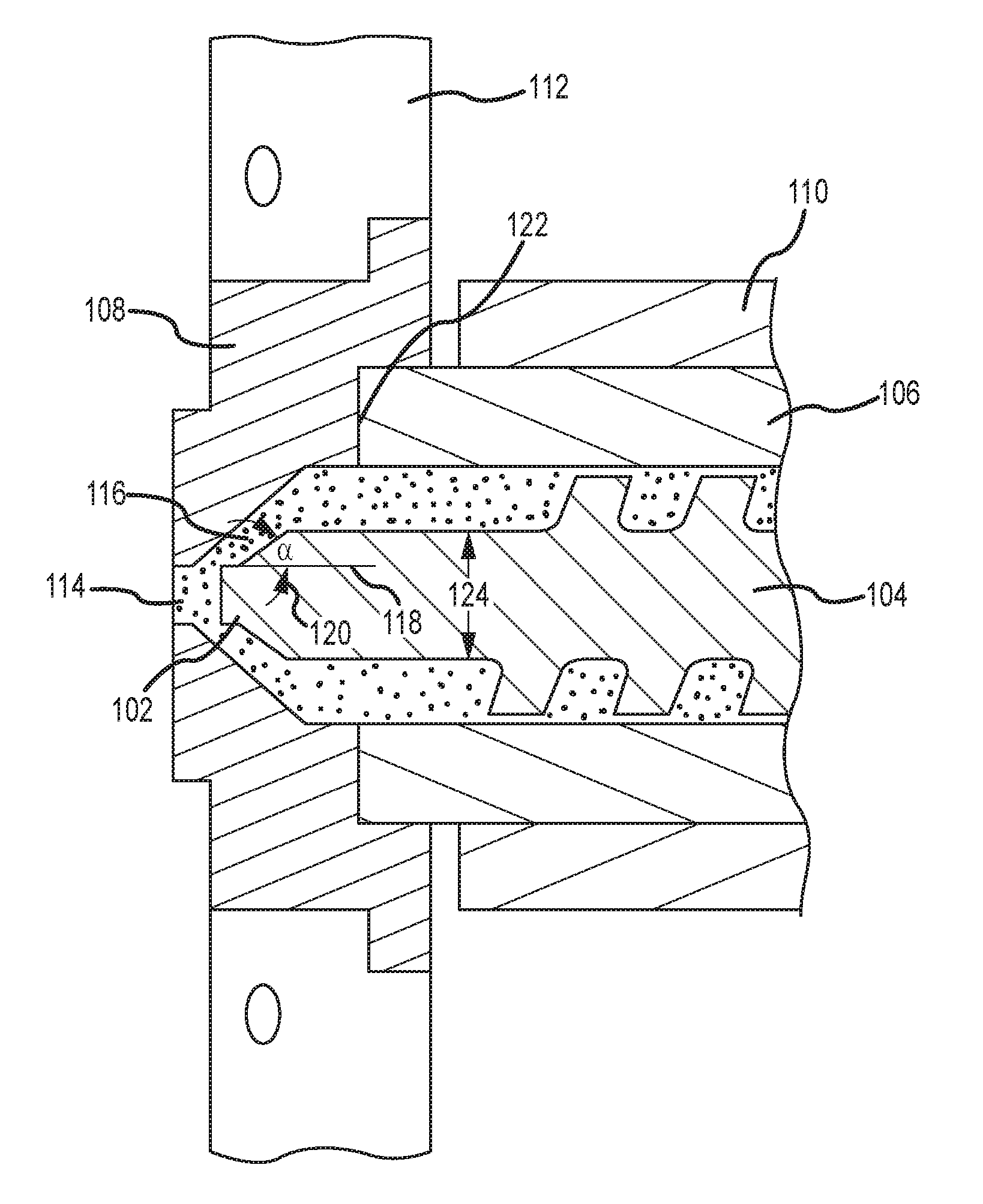
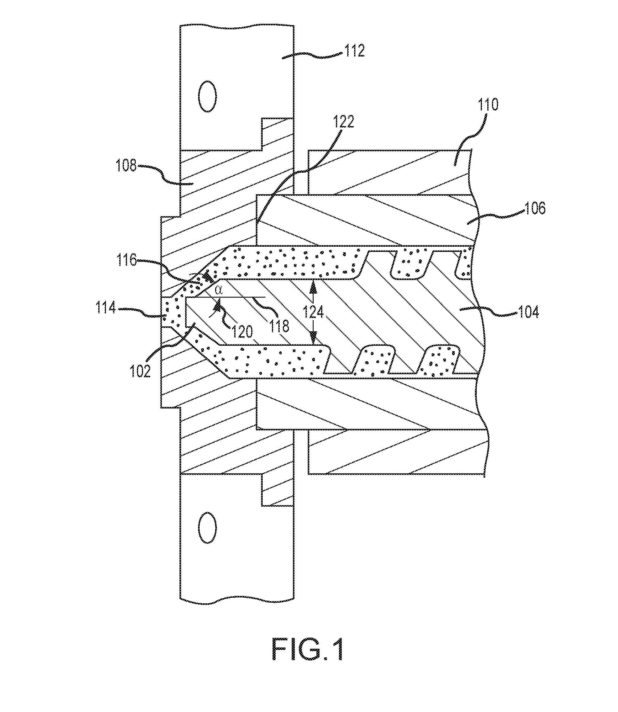
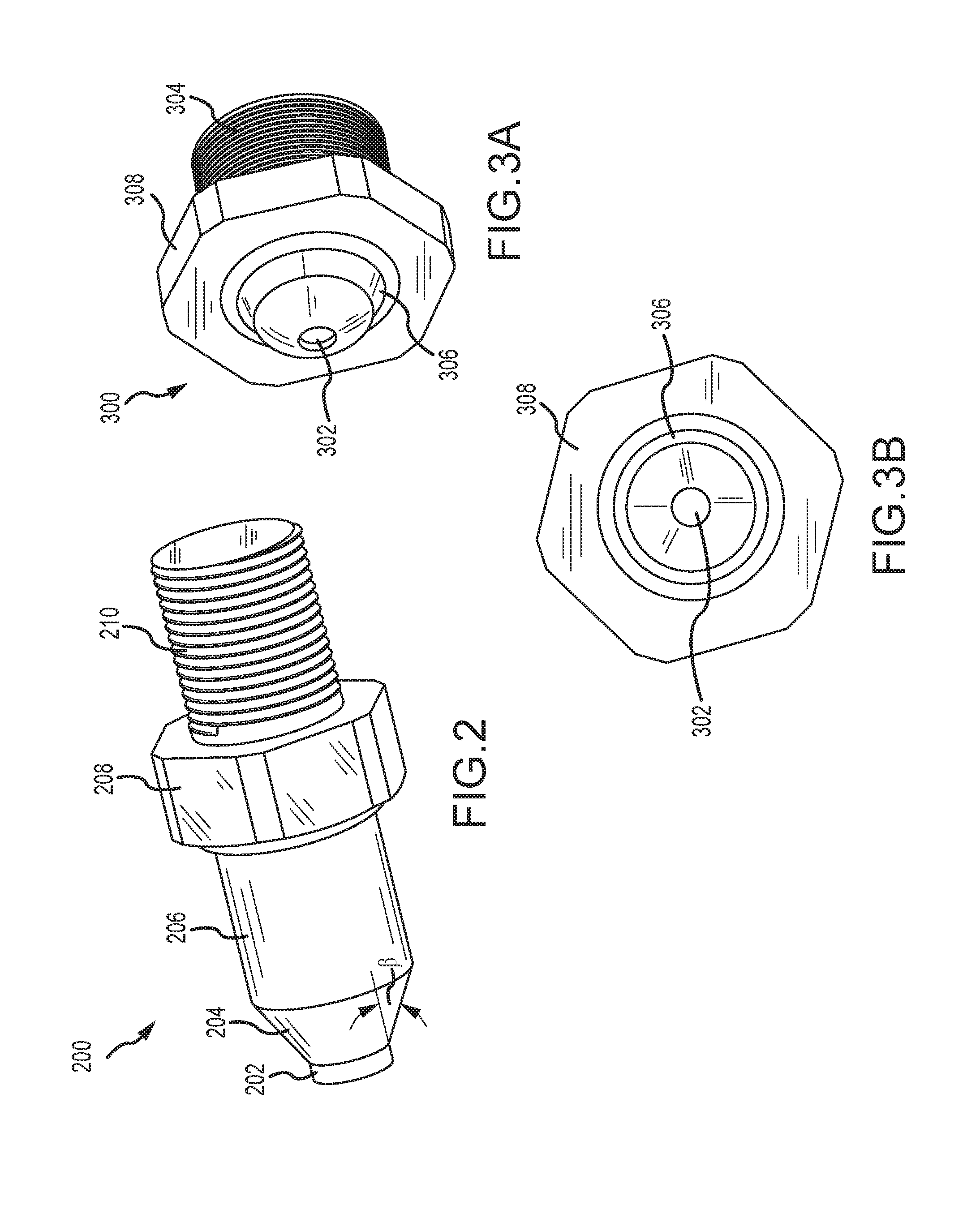
[0028]The present disclosure generally provides a screw tip configured to shut off or close a nozzle for an injection molding apparatus, machine, or system, which may be referred to herein as an extrusion-to-fill (ETF) injection molding system. The screw tip aids in more efficient injection for the ETF injection molding system because there is no cold slug to be dislodged at high pressure like the traditional injection molding system. The ETF injection molding system uses the screw tip to seal the nozzle between molding shots. The nozzle may be opened by separating a tip of an extrusion screw from an opening formed in the nozzle, and the nozzle may be closed by positioning the tip of the extrusion screw in seal...


PUM

PropertyMeasurementUnit
Fractionaaaaaaaaaa
Pressureaaaaaaaaaa
Pressureaaaaaaaaaa

Abstract

An injection molding apparatus and method of fabricating a molded part are provided. The apparatus may include a barrel, a nozzle enclosing an end of the barrel and defining an opening in fluid communication with an inside of the barrel, and an extrusion screw positioned at least partially inside the barrel and rotatable relative to the barrel. The extrusion screw may include a screw tip. Relative axial movement between the barrel and the extrusion screw may open or close the opening of the nozzle to permit or prevent, respectively, material flow through the opening of the nozzle. The method may include clamping a mold, opening a nozzle, rotating the extrusion screw to pump a molten material into the mold until the mold is filled, closing the nozzle, and unclamping the mold to release a molded part.

Description

CROSS-REFERENCES TO RELATED PATENT APPLICATIONS[0001]This patent application claims the benefit under 35 U.S.C. 119(e) of U.S. Provisional Patent Application No. 62 / 087,414, entitled “Extrude-to-Fill Injection Molding and Extrusion Screw,” and filed on Dec. 4, 2014, U.S. Provisional Patent Application No. 62 / 087,449, entitled “Nozzle Shut-off for Extrude-to-Fill Injection Molding System,” and filed on Dec. 4, 2014, and U.S. Provisional Patent Application No. 62 / 087,480, entitled “Control System for Extrude-to-Fill Injection Molding,” and filed on Dec. 4, 2014, each of which is hereby incorporated herein by reference in its entirety.FIELD[0002]The present disclosure is directed to an injection molding system. More specifically, the present disclosure is directed to an injection molding system including a nozzle closure apparatus. For example, the injection molding system may include an extrusion screw tip configured to shut off or close a nozzle.BACKGROUND[0003]A traditional injectio...

Claims


Application Information

Patent Timeline
IPC IPC(8): B29C45/23B29C45/73B29C45/74B29C45/18B29C45/40B29C48/92B29C48/30
CPCB29C45/23B29C45/18B29C45/40B29C45/74B29K2005/00B29C2045/1792B29C2045/1875B29K2105/26B29C45/73B29K2995/0008B29C45/78B29C2045/5096B29C45/5092B29C2948/924B29C2945/76006B29C2945/76257B29C2945/76381B29C2945/76498B29C2945/76665B29C2945/76859G05B2219/2624Y02P80/40B29C45/47G05B19/042B29C45/03H02K7/14B29C48/92B29C45/76B29C45/60B29C45/13B29C45/77B29C31/04
Inventor FITZPATRICK, RICHARD ERNEST
Owner EXTRUDE TO FILL
Learn More