
Apparatus and method for sensing water within a fuel-water separator assembly

a technology of fuel water separator and sensor, which is applied in the direction of separation process, filtration separation, instruments, etc., can solve the problems of poor drivability and stalling, water may form through condensation, and the internal combustion engine burning diesel-type fuel is much less tolerant of water mixed with fuel, so as to reduce the injection pressure of fuel system, reduce the maximum power and reduce the speed of the internal combustion engine

Inactive Publication Date: 2008-06-26
GM GLOBAL TECH OPERATIONS LLC
View PDF11 Cites 13 Cited by
  • Summary
  • Abstract
  • Description
  • Claims
  • Application Information

AI Technical Summary

Benefits of technology

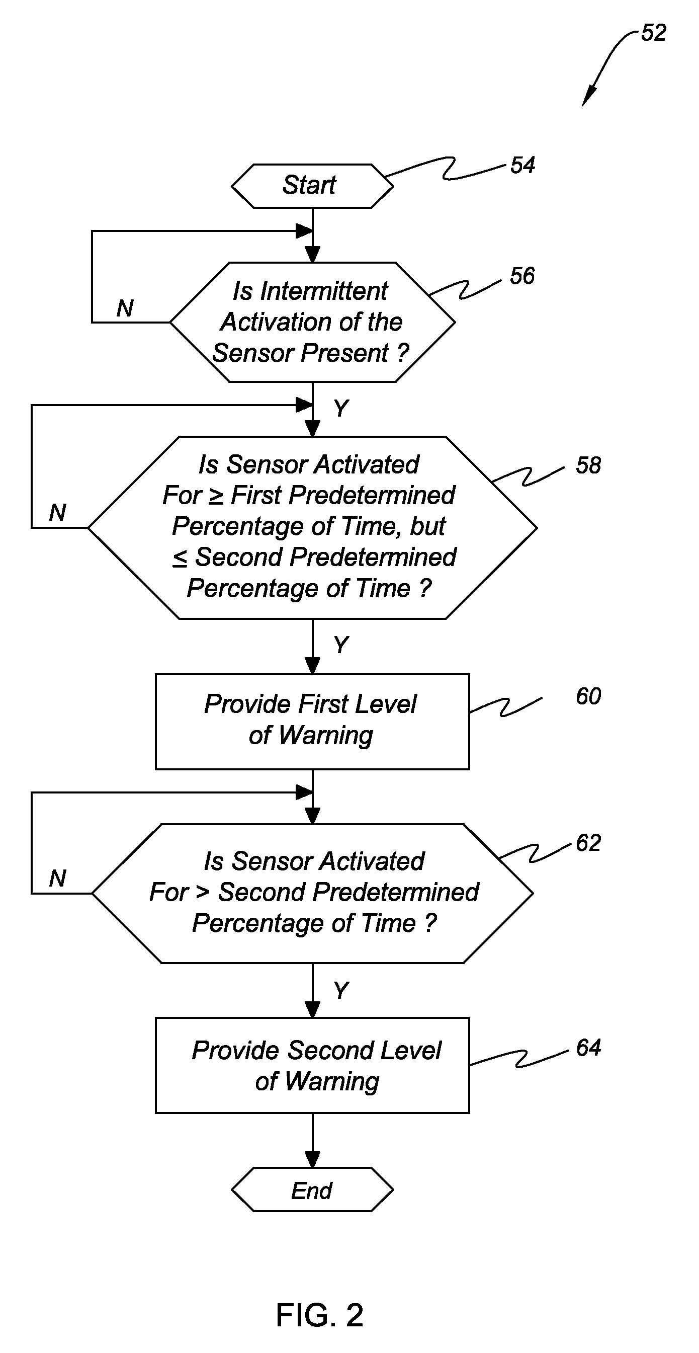
[0006]The first level of warning may be of the form of a visual and / or audible alarm. The second level of warning, which is more critical than that of the first level of warning, may be of the form of at least one of: A) shutting off the internal combustion engine; B) limiting the maximum power of the internal combustion engine; C) limiting the speed of the internal combustion engine; and D) reducing the injection pressure of the fuel system.

Problems solved by technology

Furthermore, when fuel is placed in a fuel tank of a vehicle, water may form through condensation or may be inadvertently introduced into the fuel tank.
Internal combustion engines burning gasoline-type fuels can accommodate relatively large amounts of water before issues such as poor drivability and stalling occur.
However, internal combustion engines burning diesel-type fuels are much less tolerant of water mixed with fuel.
From a performance standpoint, water mixed with fuel can cause roughness in engine operation, loss of power, and poor starting ability, particularly during cold start.

Method used


Image

  • Apparatus and method for sensing water within a fuel-water separator assembly
  • Apparatus and method for sensing water within a fuel-water separator assembly
  • Apparatus and method for sensing water within a fuel-water separator assembly

Examples


Embodiment Construction

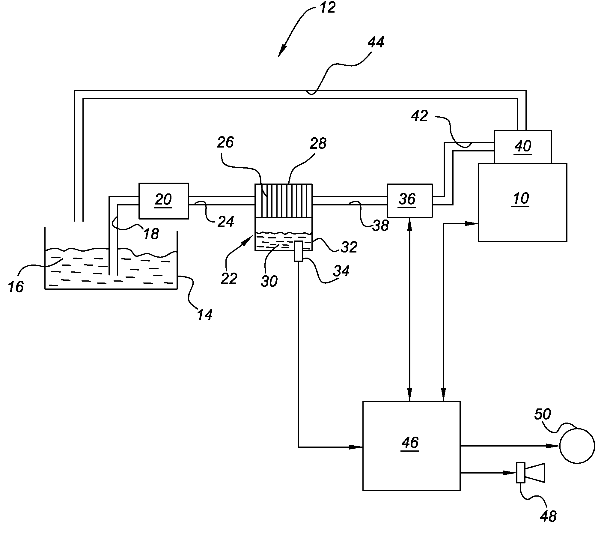
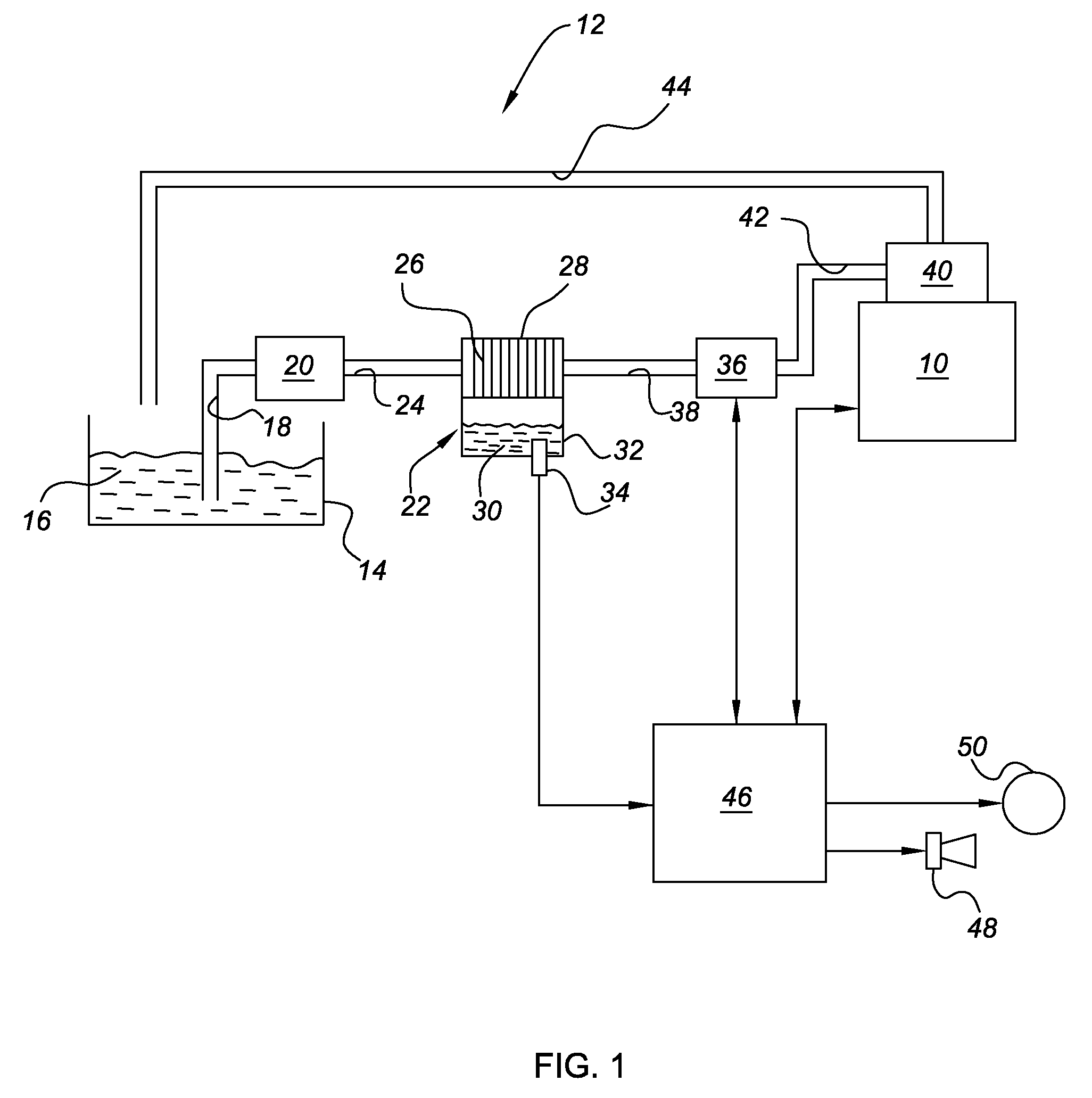
[0011]Referring to FIG. 1 there is shown an internal combustion engine 10 having a fuel system, generally indicated at 12, operatively connected thereto. The internal combustion engine 10 of FIG. 1 is a compression-ignited, diesel-fueled engine. However, those skilled in the art will recognized that the claimed invention may be applied to other types of internal combustion engines, such as spark-ignited, gasoline-fueled engines. The fuel system 12 includes a fuel reservoir or tank 14 configured to contain a predetermined amount of fuel 16. A fuel pick up 18 is mounted with respect to a fuel pump 20 and is operable to communicate fuel 16 to the fuel pump 20 where it is subsequently pressurized for delivery to a fuel-water separator assembly 22 through line 24. Although the fuel pump 20 of FIG. 1 is illustrated upstream of the fuel-water separator assembly 22, those skilled in the art will recognize that the fuel pump 20 may be placed downstream of the fuel-water separator assembly 22...


PUM

PropertyMeasurementUnit
percentage of timeaaaaaaaaaa
pressureaaaaaaaaaa
conductivityaaaaaaaaaa

Abstract

A method of sensing water within a fuel-water separator assembly disposed within a fuel system of an internal combustion engine is provided. The method includes the steps of: A) monitoring a single selectively activatable sensor within the fuel-water separator assembly to detect the presence of water; B) determining if the sensor is activated for greater than or equal to a first predetermined percentage of time, but less than or equal to a second predetermined percentage of time and providing a first level of warning if true; and C) determining if the sensor is activated for greater than the second predetermined percentage of time and providing a second level of warning if true. An apparatus configured to perform the claimed method is also disclosed.

Description

TECHNICAL FIELD[0001]The present invention relates to an apparatus and method for sensing water within a fuel-water separator assembly a fuel system operatively connected to an internal combustion engine.BACKGROUND OF THE INVENTION[0002]Water contamination in hydrocarbon liquid fuels may originate from many sources. Trace amounts of water exist in fuel due to the refining and purification processes performed at the petroleum refineries. Additionally, water may seep into fuel storage tanks or may form as condensation within storage tanks or delivery trucks. Furthermore, when fuel is placed in a fuel tank of a vehicle, water may form through condensation or may be inadvertently introduced into the fuel tank.[0003]Internal combustion engines burning gasoline-type fuels can accommodate relatively large amounts of water before issues such as poor drivability and stalling occur. However, internal combustion engines burning diesel-type fuels are much less tolerant of water mixed with fuel....

Claims


Application Information

Patent Timeline
Patent Type & Authority Applications(United States)
IPC IPC(8): G01R27/26
CPCG01N33/18
Inventor STRAUB, ROBERT D.
Owner GM GLOBAL TECH OPERATIONS LLC
Learn More