
Transducer placement and registration for image-guided sonothrombolysis

Active Publication Date: 2016-06-02
KONINKLJIJKE PHILIPS NV
View PDF9 Cites 114 Cited by
  • Summary
  • Abstract
  • Description
  • Claims
  • Application Information

AI Technical Summary

Benefits of technology

The patent is about a method for treating blood clots using ultrasound. The skull is highly absorbent, so to effectively treat clots, the ultrasound needs to have a wide coverage and high intensity. The treatment involves insonifying a large area around the clot using a broad beam, followed by a pause to allow bubbles to return to the area. The method is also able to compensate for small displacements or misalignment of the treatment beam with the clot by adjusting the position of the transducers. The use of a matrix transducer with limited elements and high power capabilities makes the method less expensive and more efficient.

Problems solved by technology

For axial resolution, broadband transducers are usually used, which may be less efficient at overall power transmission.
Imaging transducers are not designed to be particularly efficient, as image quality is the driving concern and input power rarely considered.
For instance, the beam can be defocused, but this significantly reduces the local instantaneous power in the ROI.2. The beam (with relatively narrow coverage) can be step-scanned around the region of interest, but a beam in one location is likely to destroy bubbles in adjacent locations, which may require much longer therapy times while the bubbles replenish the ROI.

Method used


Image

  • Transducer placement and registration for image-guided sonothrombolysis
  • Transducer placement and registration for image-guided sonothrombolysis
  • Transducer placement and registration for image-guided sonothrombolysis

Examples


Embodiment Construction

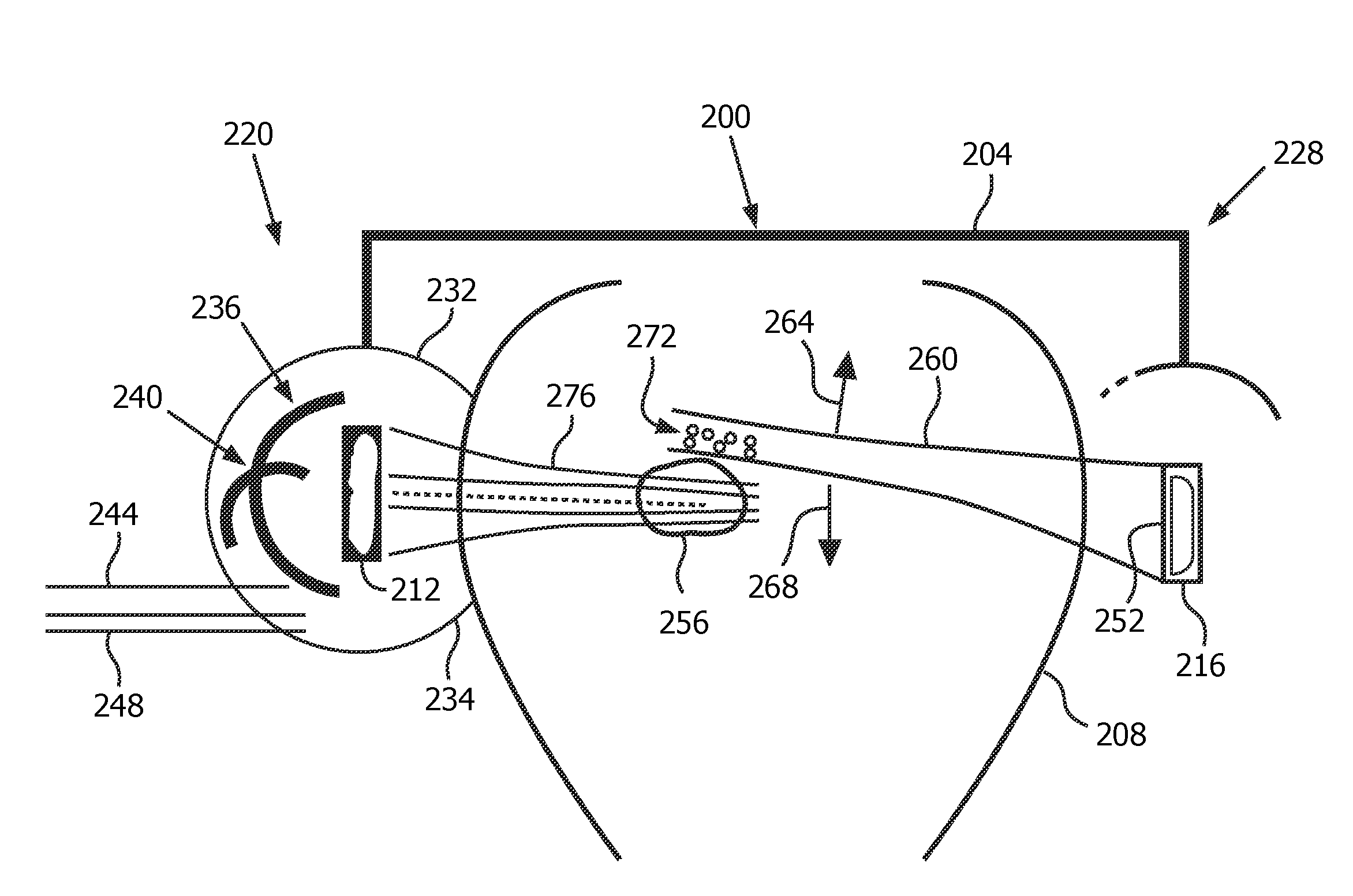
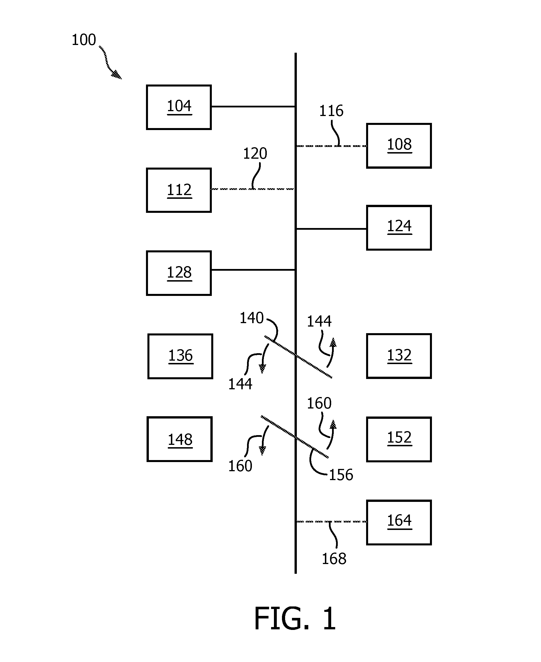
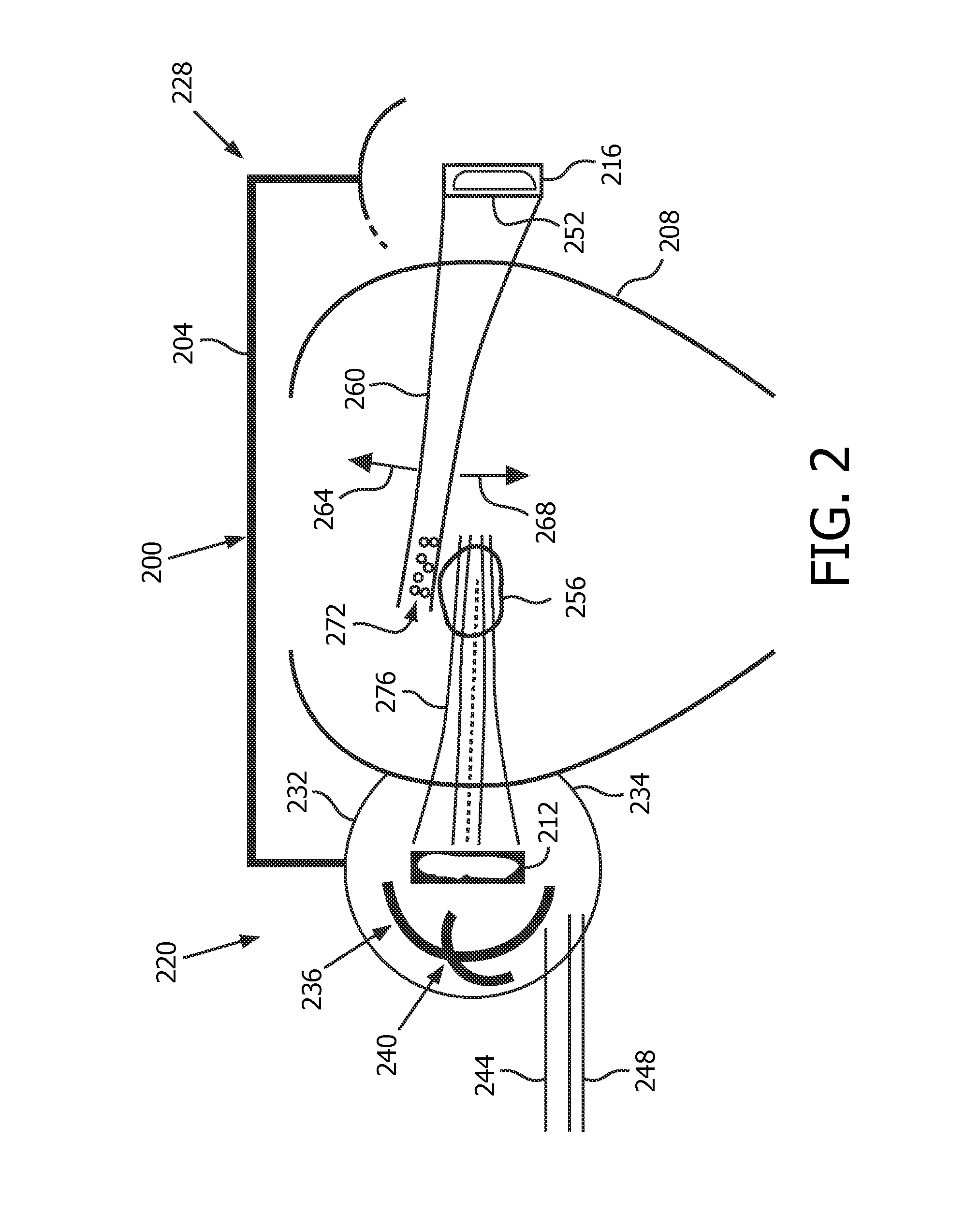
[0048]FIG. 1 depicts, in illustrative and non-limitative example, an apparatus 100 serving as a combination imaging and therapy system. It includes a controller 104, a receiving-element-based (REB) registration module 108, and / or a microbubble-activity-based (MAB) registration module 112. The broken lines 116, 120 to the REB and MAB registration modules are to imply that the two modules 104, 108 are alternatives or can be operational within the same device. Also part of the apparatus 100 are a cavitation processor 124 which is mentioned herein above, and a main ultrasound system 128 that corresponds to FIG. 1 of the Browning application with the changes discussed herein above. The main ultrasound system 128 therefore contains the user interface 38, the display 40, etc. in FIG. 1 of the Browning application. An additional part of the apparatus 100 is an imaging subsystem 132 and its complementary detachable therapy subsystem 136. A first illustrative line segment 140 is rotatable, ac...


PUM


Abstract

An apparatus for ultrasound irradiation of a body part (208) includes a first ultrasound transducer (216), and a second ultrasound transducer (212) mounted oppositely, and is configured: a) such that at least two ultrasound receiving elements, for determining a relative orientation of the first to the second transducer, are attached to the first transducer; b) for a beam, from the first transducer, causing cavitation, and / or bubble destruction of systemically circulating microbubbles, within the body part; or c) both with the attached elements and for the causing. The apparatus registers, with said first transducer, the second transducer, by using as a reference respectively the features a) and / or b). A detachable subsystem includes either a therapy or imaging transducer, to form a combination imaging and therapy system, the subsystem being configured for removable coupling to correspondingly an imaging or therapy subsystem comprising a head frame (204) to which is mounted an imaging or therapy transducer, the imaging or therapy subsystem for registering the imaging or therapy transducer, one to the other, by the above method.

Description

FIELD OF THE INVENTION[0001]The present invention relates to registering one ultrasound transducer to another and, more particularly, to registering transducers mounted on opposite sides of a body part.BACKGROUND OF THE INVENTION[0002]It has been known for many years that ultrasound in combination with thrombolytic drugs, in particular tissue plasminogen activator (tPA) can aid in the dissolution of blood clots that cause ischemic stroke. However, tPA has many side effects and can be deadly when used in a hemorrhagic (bleeding) stroke patient and so requires a CT to rule out hemorrhage before its use. Ultrasound in combination with microbubble contrast agents has also been shown to lyse blood clots with potentially fewer adverse effects. This effect is commonly referred to as sonothrombolysis (STL).[0003]Transcranial imaging has long been used to diagnose cerebrovascular diseases such as stroke with diagnostic ultrasound systems. Strokes nearly always occur on one side of the brain ...

Claims


Application Information

Patent Timeline
IPC IPC(8): A61M37/00A61B8/08A61B8/00
CPCA61M37/0092A61B8/4254A61B8/4483A61N2007/0052A61B8/085A61B8/4209A61B8/461A61B8/5238A61N7/00A61N2007/0039A61B2034/2063A61B2090/378A61B8/06A61B8/0816A61B8/481
Inventor POWERS, JEFFRY EARLSHI, WILLIAM TAOFRASER, JOHN DOUGLASSEIP, RALFVIGNON, FRANCOIS GUY GERARD MA
Owner KONINKLJIJKE PHILIPS NV
Learn More