Wing and turbine configuration for power plant

a technology of power plants and turbines, applied in the field of power plants, can solve the problems of increasing the cost of submersible plants, complex design and manufacture, etc., and achieve the effects of reducing the distance between the centre of gravity of the vehicle and the centre of buoyancy, increasing the structure, and increasing the speed of the fluid flowing through the turbin

Active Publication Date: 2016-05-26
MINESTO
View PDF7 Cites 0 Cited by
  • Summary
  • Abstract
  • Description
  • Claims
  • Application Information

AI Technical Summary

Benefits of technology

[0022]By having the first and second wing parts angles be dihedral angles the vehicle will be stabilized due to the dihedral effect. This removes the need for structural components such as struts in order to stabilize the vehicle. In this configuration the nacelle is attached to an upper side of the wing of the vehicle as the wing are angled upwards. The tether can then be attached to the vehicle by being attached to a coupling in the wing of the vehicle such that no forces from the tether are lead through the nacelle.
[0023]By moving the nacelle above the wing the distance between t

Problems solved by technology

This is a however a system involving several relatively fragile parts and a number of couplings and

Method used


Image

  • Wing and turbine configuration for power plant
  • Wing and turbine configuration for power plant
  • Wing and turbine configuration for power plant

Examples


Embodiment Construction

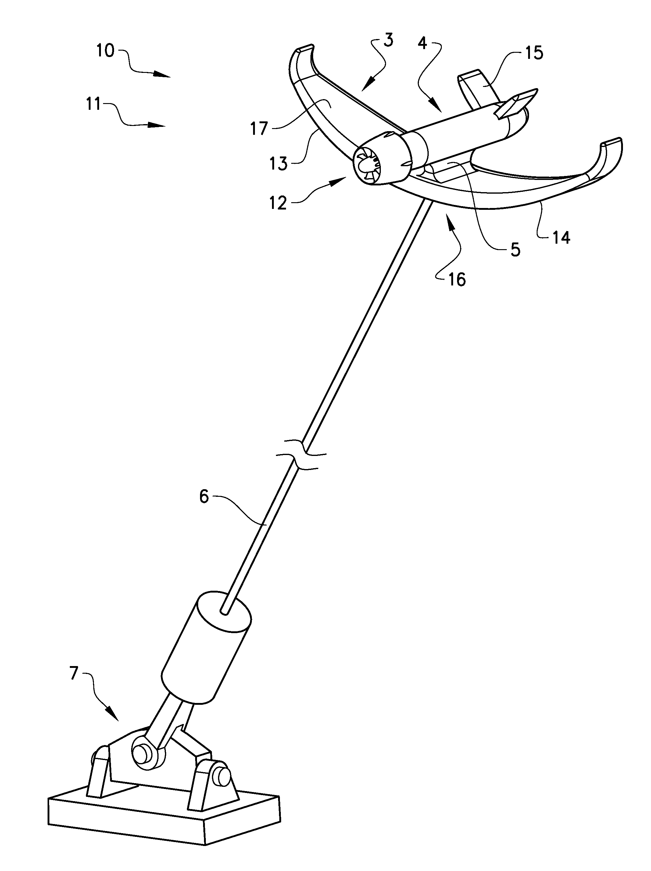
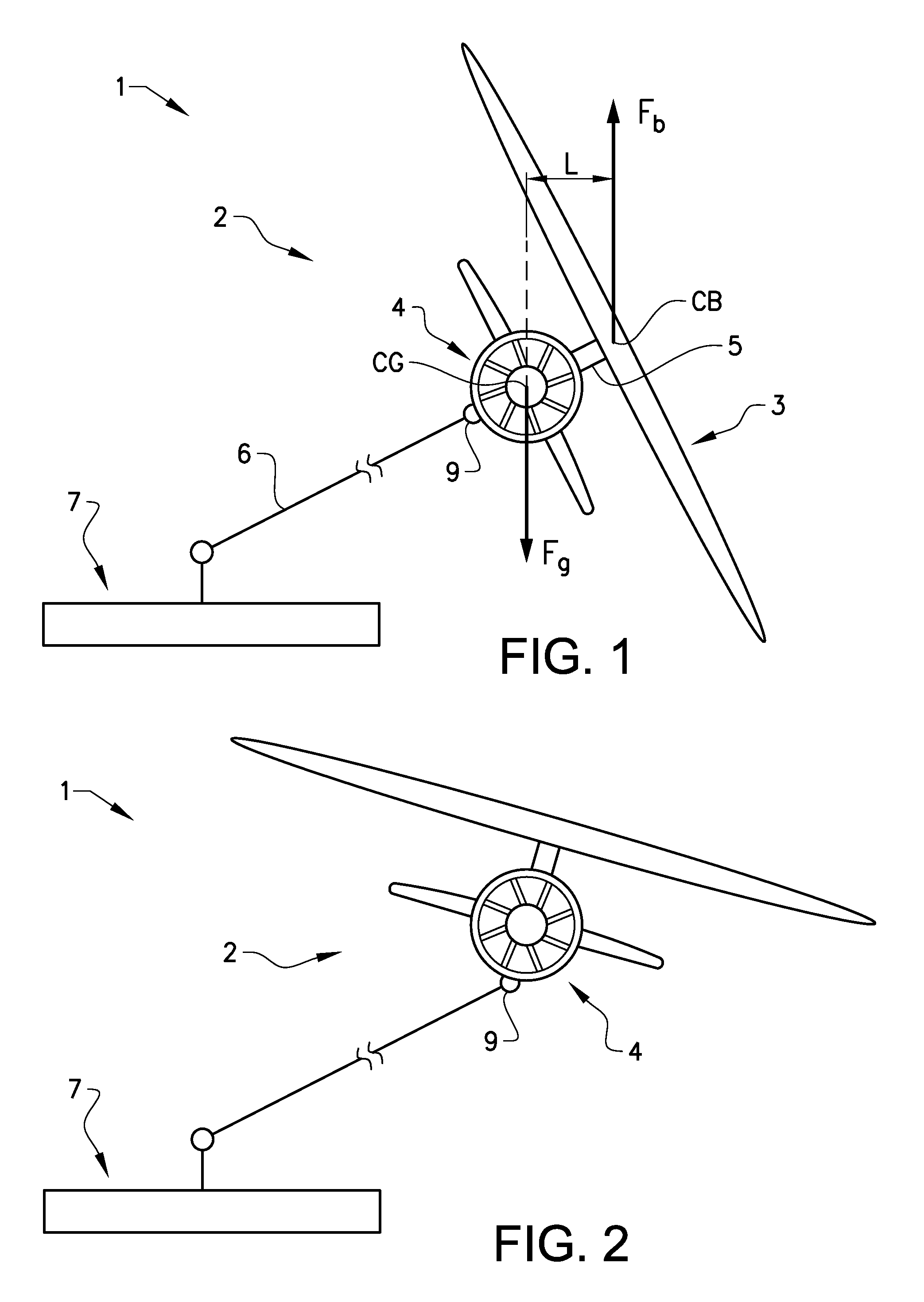
[0043]FIG. 1 schematically shows a prior art power plant 1 comprising a prior art vehicle 2. The prior art vehicle 2 comprises a wing 3 and a nacelle 4 comprising a generator. The nacelle 4 is attached to a turbine. The nacelle 4 is attached to the wing 3 by means of a pylon 5 attached to an underside of the wing 3. A tether 6 attaches the prior art vehicle 2 to a structure 7. The prior art vehicle 2 comprises a centre of gravity (CG) and a centre of buoyancy (CB). In the prior art vehicle 2 the CG is located near the nacelle 4 and the CB is located near the wing 3. The placements of the GG and CB are merely illustrative in order to demonstrate a disadvantage of the prior art vehicle 2. A downward gravitational force Fg is exerted on the prior art vehicle 2 from the CG. A buoyancy force Fb is exerted on the prior art vehicle 2 from the CB. The prior art vehicle is designed to have the possibility to adjust the overall buoyancy to be neutral in the surrounding fluid. The uneven distr...


PUM


Abstract

A power plant includes a structure and a vehicle having at least one wing including a first wing part and a second wing part. The vehicle is arranged to be secured to the structure by at least one tether. The vehicle is arranged to move in a predetermined trajectory by a fluid stream passing the wing. The vehicle includes at least one turbine connected to a nacelle having a generator. At least the first wing part is arranged at a first angle relative to a horizontal centre line of the wing. The nacelle is arranged to be attached to a surface of the wing facing the direction in which the first wing part is angled.

Description

CROSS REFERENCE TO RELATED APPLICATIONS[0001]This application is a U.S. National Stage patent application of PCT / SE2014 / 050893, filed on Jul. 12, 2013, the entire contents of which are incorporated herein by reference.FIELD OF THE INVENTION[0002]The invention relates to a power plant for producing electrical power. The power plant comprises a structure and a vehicle comprising at least one wing comprising a first wing part and a second wing part. The vehicle is arranged to be secured to the structure by means of at least one tether. The vehicle is arranged to move in a predetermined trajectory by means of a fluid stream passing the wing. The vehicle comprises at least one turbine connected to a nacelle comprising a generator.BACKGROUND OF THE INVENTION[0003]Power plants for generating electrical power are known in the art, see for instance EP 1816345. In EP 1816345 the power plant comprises a vehicle attached to a structure moving along a trajectory being powered by tidal currents.[...

Claims


Application Information

Patent Timeline
IPC IPC(8): F03B17/06B63G8/00B63G8/18F03B13/26
CPCF03B17/061B63G8/18B63G8/001F03B13/264F03D9/28F05B2240/917F05B2240/9174F05B2240/921Y02E10/30Y02E10/72Y02E10/728F03D9/257F03D9/32Y02E10/20
Inventor QUAPPEN, ARNE
Owner MINESTO
Why Eureka
Try Eureka