
Power amplifier for amplifying radio frequency signal

a radio frequency signal and power amplifier technology, applied in the field ofsignal amplification, can solve the problems of increasing the size, cost, complexity etc., and achieve the effects of reducing the size and reducing the cost of the mobile devi

Active Publication Date: 2016-05-19
MICROSOFT TECH LICENSING LLC
View PDF2 Cites 17 Cited by
  • Summary
  • Abstract
  • Description
  • Claims
  • Application Information

AI Technical Summary

Benefits of technology

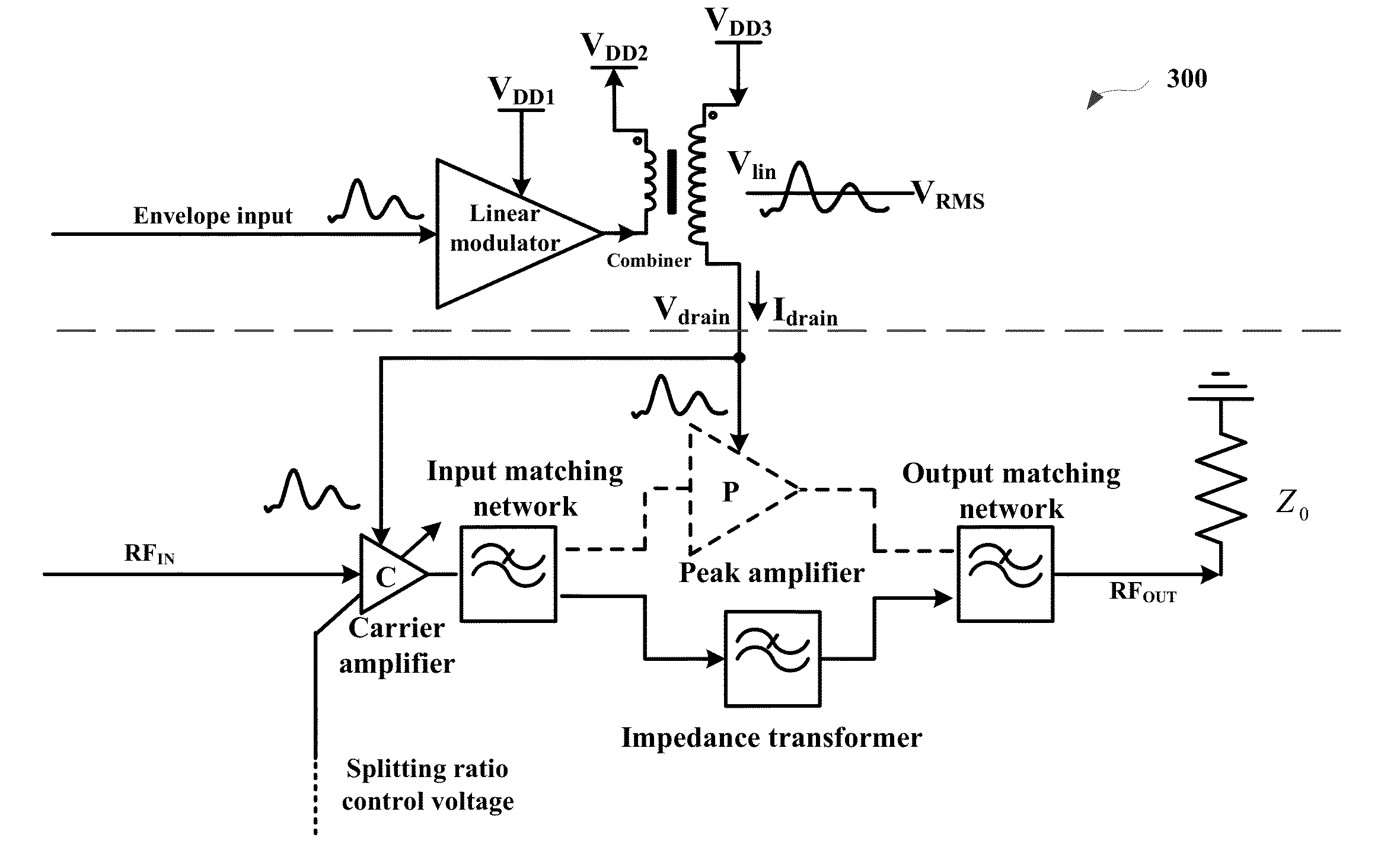
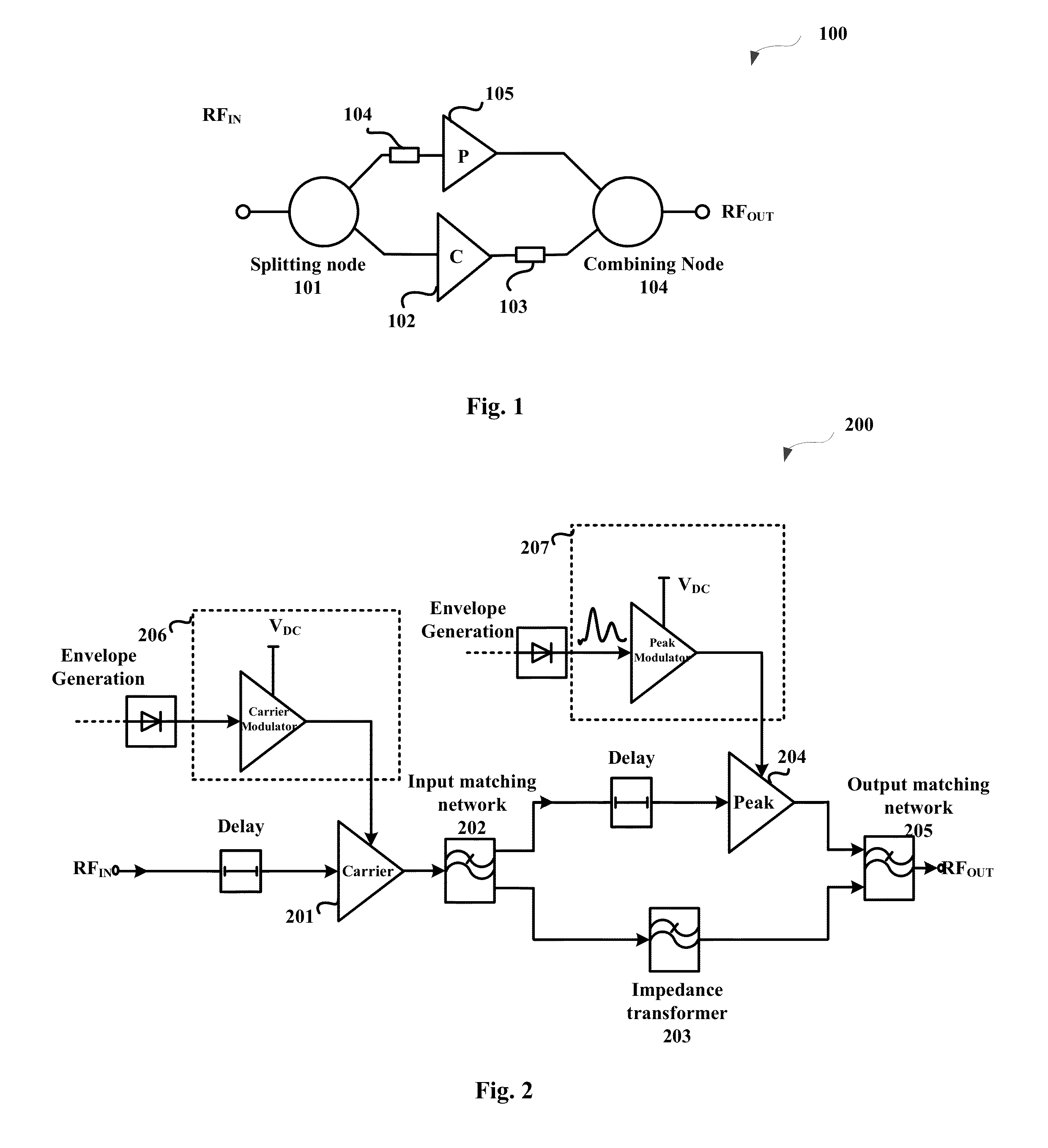
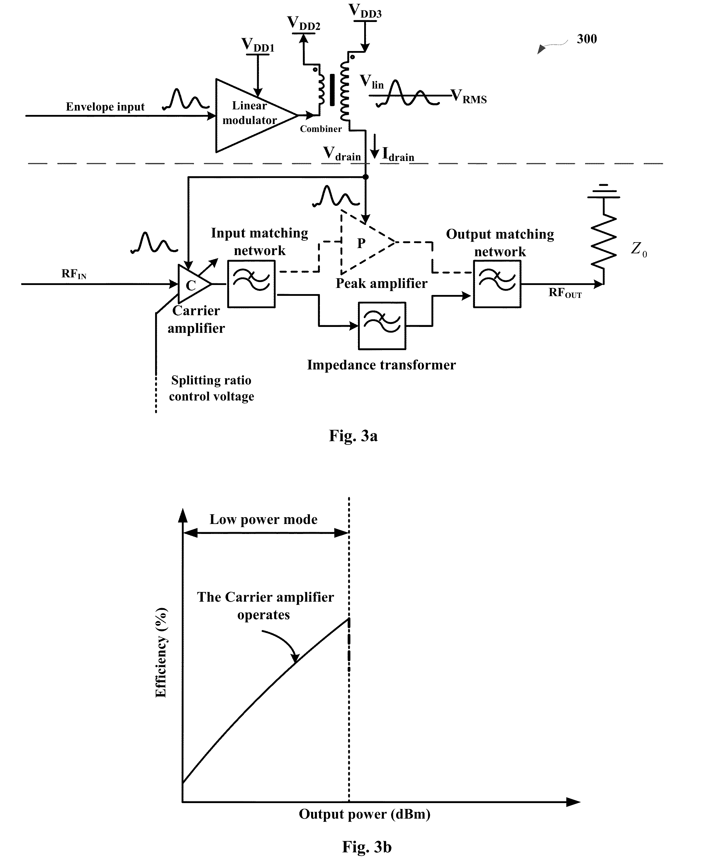
The present invention provides a flexible design for power amplifiers that can tolerate high peak power back offs and offers wider bandwidth and efficiency optimization. By using a serial connection between an envelope tracking carrier and peak amplifiers, a natural power gain increase and profile reduction in the whole transmitter can be achieved. Additionally, phase matching between the peak amplifier and the impedance transformer is easier to achieve as the short term and long term memory effects of two active devices are more difficult to be compensated and linearized. The serial connection of carrier and peak amplifiers may form a line-up arrangement, which may enable the driver stage to further improve the efficiency characteristics of the transmitter chain.

Problems solved by technology

However, it would be hard to dispose such number of separated low voltage and impedance PAs in a single mobile device, which inevitably increases the size, cost, and complexity of the mobile device.

Method used


Image

  • Power amplifier for amplifying radio frequency signal
  • Power amplifier for amplifying radio frequency signal
  • Power amplifier for amplifying radio frequency signal

Examples


Embodiment Construction

[0038]The present disclosure will now be described more fully hereinafter with reference to the accompanying drawings, in which certain embodiments of the present disclosure are shown. This disclosure may, however, be embodied in many different forms and should not be construed as limited to the embodiments set forth herein; rather, these embodiments are provided by way of example so that this disclosure will be thorough and complete, and will fully convey the scope of the present disclosure to those skilled in the art. Like numbers refer to like elements throughout the specification.

[0039]Generally, all terms used in the claims are to be interpreted according to their ordinary meaning in the technical field, unless explicitly defined otherwise herein. All references to “a / an / the element, apparatus, component, means, step, etc.” are to be interpreted openly as referring to at least one instance of the element, apparatus, component, means, step, etc., unless explicitly stated otherwi...


PUM


Abstract

Power amplifiers for amplifying a radio frequency signal are provided. The power amplifier may include an envelope tracking power supply, a carrier amplifier coupled with the envelope tracking power supply and configured to amplify the radio frequency signal, an input matching network configured to split the amplified radio frequency signal from the carrier amplifier such that one part of the amplified radio frequency signal passes along a peak amplifier path and another part of the amplified radio frequency signal passes along an impedance transformer path, a peak amplifier coupled with the envelope tracking power supply and configured to amplify the one part of the amplified radio frequency signal from the input matching network, an impedance transformer configured to perform impedance transformation on the other part of the amplified radio frequency signal from the input matching network, an output matching network configured to combine the output of the peak amplifier and the impedance transformer, wherein the peak amplifier is configured to be switched off in a lower power mode and switched on in a high power mode based at least in part on an input power level of the radio frequency signal. With the claimed solutions, more powerful and efficient power amplifiers that are capable of operating over broader frequency ranges may be achieved.

Description

RELATED APPLICATIONS[0001]This application claims priority to Chinese Application No. 201410643351.4, filed on Nov. 14, 2014, and entitled “POWER AMPLIFIER FOR AMPLIFYING RADIO FREQUENCY SIGNAL.” This application claims the benefit of the above-identified application, and the disclosure of the above-identified application is hereby incorporated by reference in its entirety as if set forth herein in full.FIELD OF THE INVENTION[0002]Example embodiments of the present disclosure generally relate to signal amplification. More particularly, example embodiments of the present disclosure relate to power amplifiers (“PAs”) for amplifying a radio frequency (“RF”) signal.BACKGROUND OF THE INVENTION[0003]The following description of background art may include insights, discoveries, understandings or disclosures, or associations together with disclosures not known to the relevant art prior to the present disclosure but provided by the present disclosure. Some such contributions of the present d...

Claims


Application Information

Patent Timeline
Patent Type & Authority Applications(United States)
IPC IPC(8): H03F1/02H03F3/21H03F3/19H03F1/56
CPCH03F1/0288H03F1/565H03F3/21H03F2200/387H03F2200/102H03F2200/451H03F2200/222H03F3/19H03F1/0227H03F3/195H03F3/245H03F2200/432H03F2200/405H03F2200/408H03F2200/411H03F2200/318H03F2200/111H03F1/0222H03F3/191
Inventor WANG, ZHANCANG
Owner MICROSOFT TECH LICENSING LLC
Learn More