
Method for controlling a power stage

a power converter and power stage technology, applied in the direction of instruments, ac network circuit arrangements, apparatus without intermediate ac conversion, etc., can solve the problems of excessive over/undershoot and ringing of controlled voltage, unsatisfactory perturbation of the output voltage of the dc-dc converter, and often uncertain value of the output bulk capacitance, etc., to achieve the effect of superior respons

Inactive Publication Date: 2016-05-19
IDT EURO GMBH
View PDF4 Cites 7 Cited by
  • Summary
  • Abstract
  • Description
  • Claims
  • Application Information

AI Technical Summary

Benefits of technology

The present invention provides a method for controlling a power stage with a superior response and a more robust power compensator. The method identifies parameters of the power stage during ramp up of the power converter and adjusts the control law accordingly to achieve the desired output voltage. This re-parameterization and scaling of the compensator can be done to cater for a variety of variations and design objectives. The technical effects of the invention are better performance and efficiency of power converters.

Problems solved by technology

In DC-DC converter applications the value of the output bulk capacitance is often uncertain.
In demanding transient applications such as point of load (POL), this uncertainty can lead to excessive over / under-shoot and ringing of the controlled voltage.
This is a particular problem in POL modules, but exists in many DC-DC applications.
In many cases this introduces a perturbation on to the output voltage of the DC-DC converter that can be undesirable.
This is a particular problem with non-parametric identification, whereby a test signal is usually introduced.
In parametric identification a lack of persistent excitation may result in the need for an injected signal to improve identification.
Furthermore, the quality of the estimate can be poor in circumstances in which there is a lack of persistent excitation or an unstable system, leading to a poorly compensated control system or requiring the introduction of a disturbance to excite the system.
Several disadvantages exist with known methods including the high computational complexity involved in the calculation of the compensation parameters, making IC implementation more costly.
This involves a matrix inversion and therefore is complex in hardware.

Method used


Image

  • Method for controlling a power stage
  • Method for controlling a power stage
  • Method for controlling a power stage

Examples


Embodiment Construction

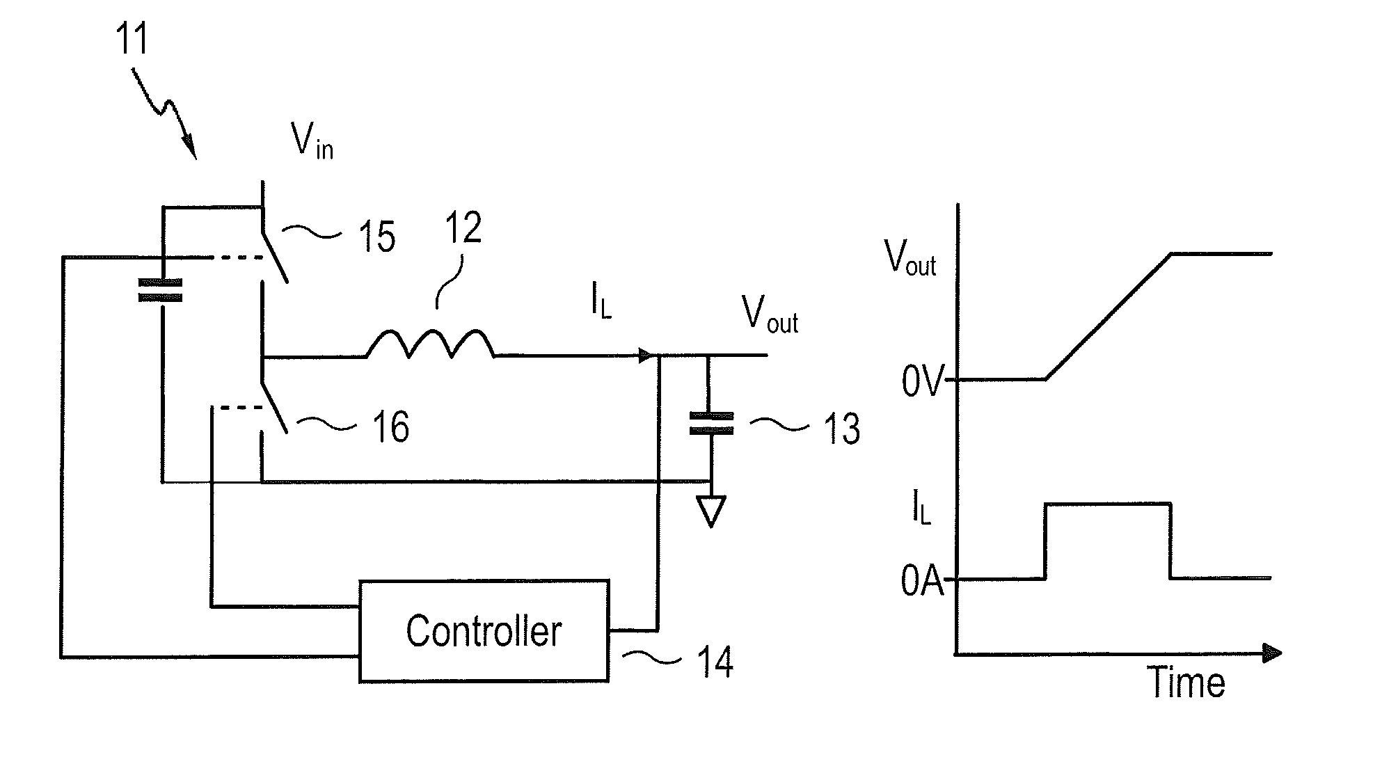
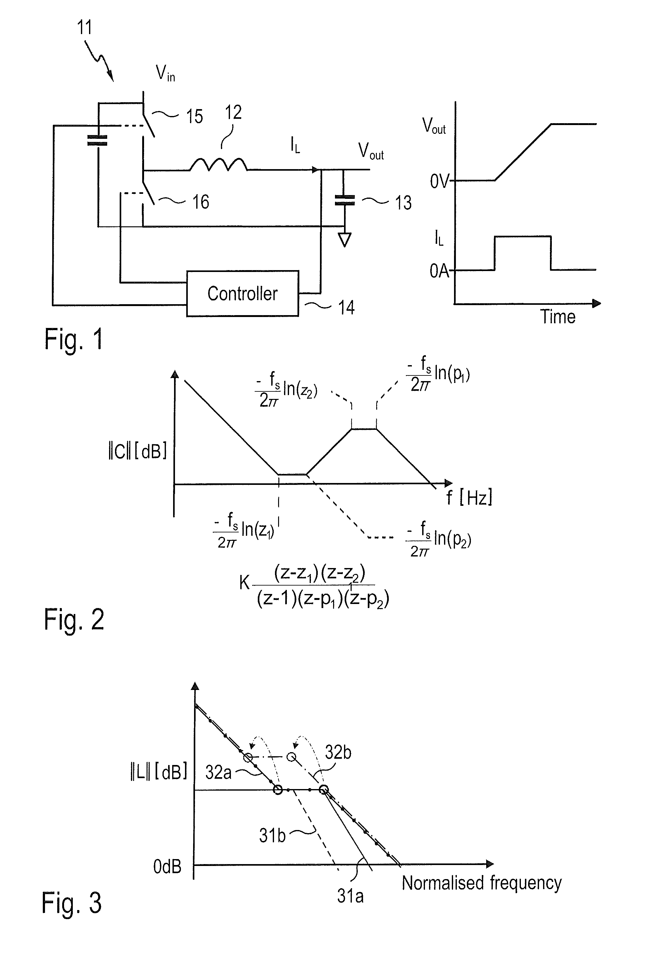
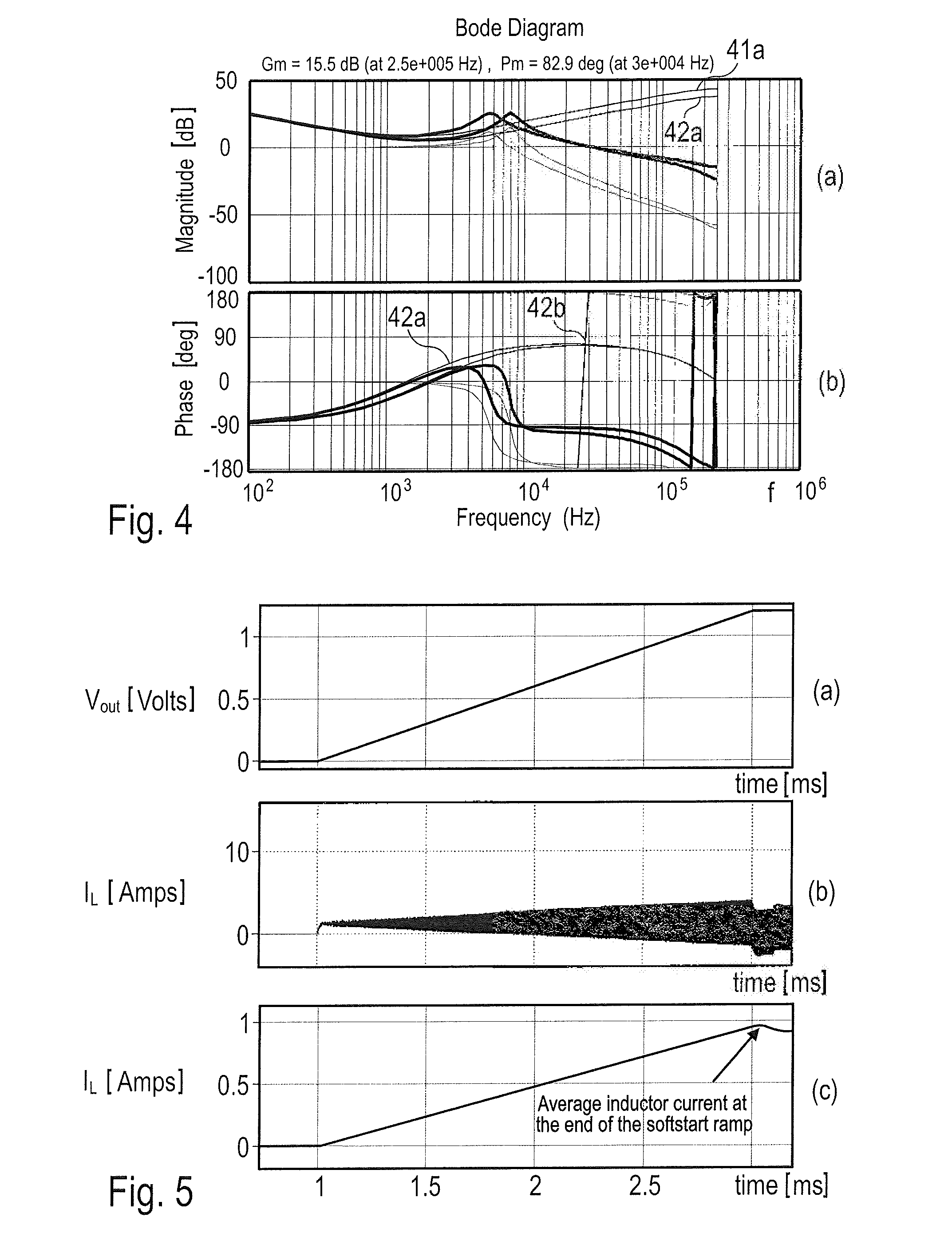
[0039]FIG. 1 shows a soft-start mechanism of a DC-DC converter comprising switched power stage 11, said power stage comprising an inductor 12 an output capacitor 13 and a compensator 14 implementing a control law for controlling the switches 15, 16 of the power stage 11. During the soft-start ramp-up the inductor current must charge the output capacitor 13. Load devices connected to the DC-DC converter are usually in active reset prior to the output voltage reaching its desired setpoint and, therefore, it can be assumed that they draw no current during the soft-start ramp up. As the total charge applied to the capacitor is proportional to the final voltage and its capacitance C, the capacitance C can be estimated as a function of the applied charge. The applied charge can easily be determined from the average current iL,AVG applied during the soft-start ramp and the ramp time (ΔT), where ΔV is the difference between the start-of-ramp and end-of ramp voltage. The estimated capacitanc...


PUM


Abstract

In a control method for a power converter, an output voltage is generated according to a control law controlling a switched power stage. During ramp up of the power converter, at least one parameter of the power stage is identified, and the control law is adapted to the identified at least one parameter of the power stage for operating the power converter.

Description

Technical Field[0001]The present invention relates to a method for controlling a power stage and related power converter. The present invention specifically relates to method for controlling a DC-DC power converter.PRIOR ART[0002]In DC-DC converter applications the value of the output bulk capacitance is often uncertain. In demanding transient applications such as point of load (POL), this uncertainty can lead to excessive over / under-shoot and ringing of the controlled voltage. This is a particular problem in POL modules, but exists in many DC-DC applications.[0003]Module manufacturers have attempted to solve this problem, for example, by allowing the module user to adjust the compensation of the POL module [1, 2].[0004]Adaptive control techniques involve the steps of parameter identification and controller design. Researchers have used adaptive control techniques [3 to 6], using various methods of identifying the parameters of the power stage and using the estimate of those values ...

Claims


Application Information

Patent Timeline
IPC IPC(8): H02M3/04H02M1/36
CPCH02M1/36H02M3/04H02M3/156H02M3/157
Inventor KELLY, ANTHONYWARD, ADRIAN
Owner IDT EURO GMBH
Learn More