
Projectile weapon training apparatus using visual display to determine targeting, accuracy, and/or reaction timing

a projectile weapon and visual display technology, applied in the field of projectile weapon training system, can solve the problems of not providing realistic experience for trainees to replicate, trainees are therefore not able to accurately simulate realistic surroundings, and trainees are not able to replicate targeting experien

Active Publication Date: 2016-05-19
LATTS LLC
View PDF9 Cites 19 Cited by
  • Summary
  • Abstract
  • Description
  • Claims
  • Application Information

AI Technical Summary

Benefits of technology

The patent describes a method for measuring a user's accuracy in hitting a valid target and avoiding hitting an invalid target with a projectile. The method involves sensing the location of the impact and calculating the user's cognitive response based on this information. The technical effect of the patent is to provide a quantitative measure of a user's performance when using a projectile.

Problems solved by technology

While this may provide an element of safety to the training scenario, it does not provide a realistic experience for the trainee which replicates the use of an unmodified weapon.
The trainee is therefore not able to replicate the targeting experience which would be utilized in the context outside the training system.
However, they are unable to accurately simulate realistic surroundings that may be present in the case of a weapon discharge outside the context of the targeting range.
Additionally, traditional targeting ranges are limited in the feedback available to a trainee, such as temporal recognition of an accurate contact with a target.

Method used


Image

  • Projectile weapon training apparatus using visual display to determine targeting, accuracy, and/or reaction timing
  • Projectile weapon training apparatus using visual display to determine targeting, accuracy, and/or reaction timing
  • Projectile weapon training apparatus using visual display to determine targeting, accuracy, and/or reaction timing

Examples


Embodiment Construction

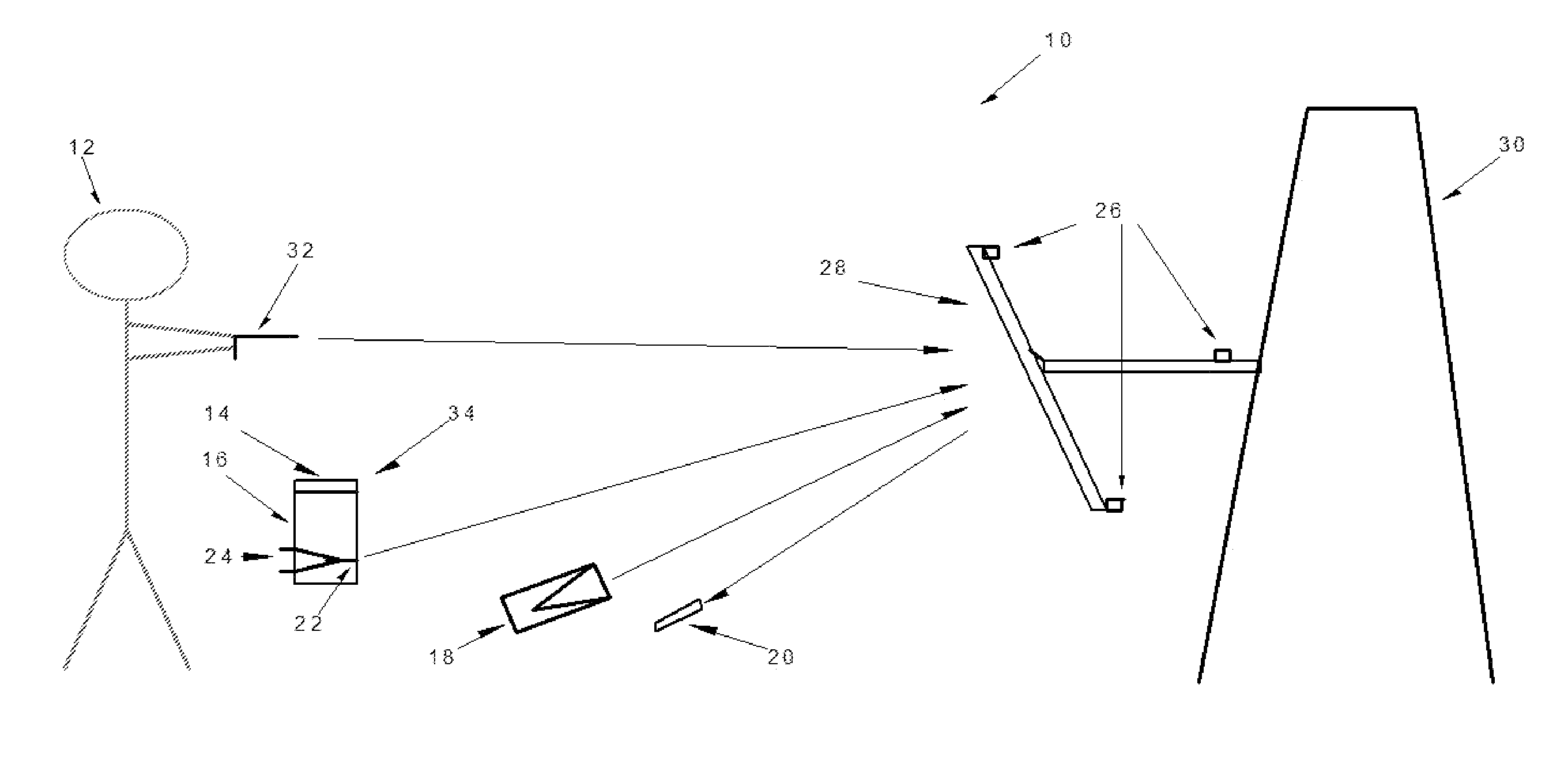
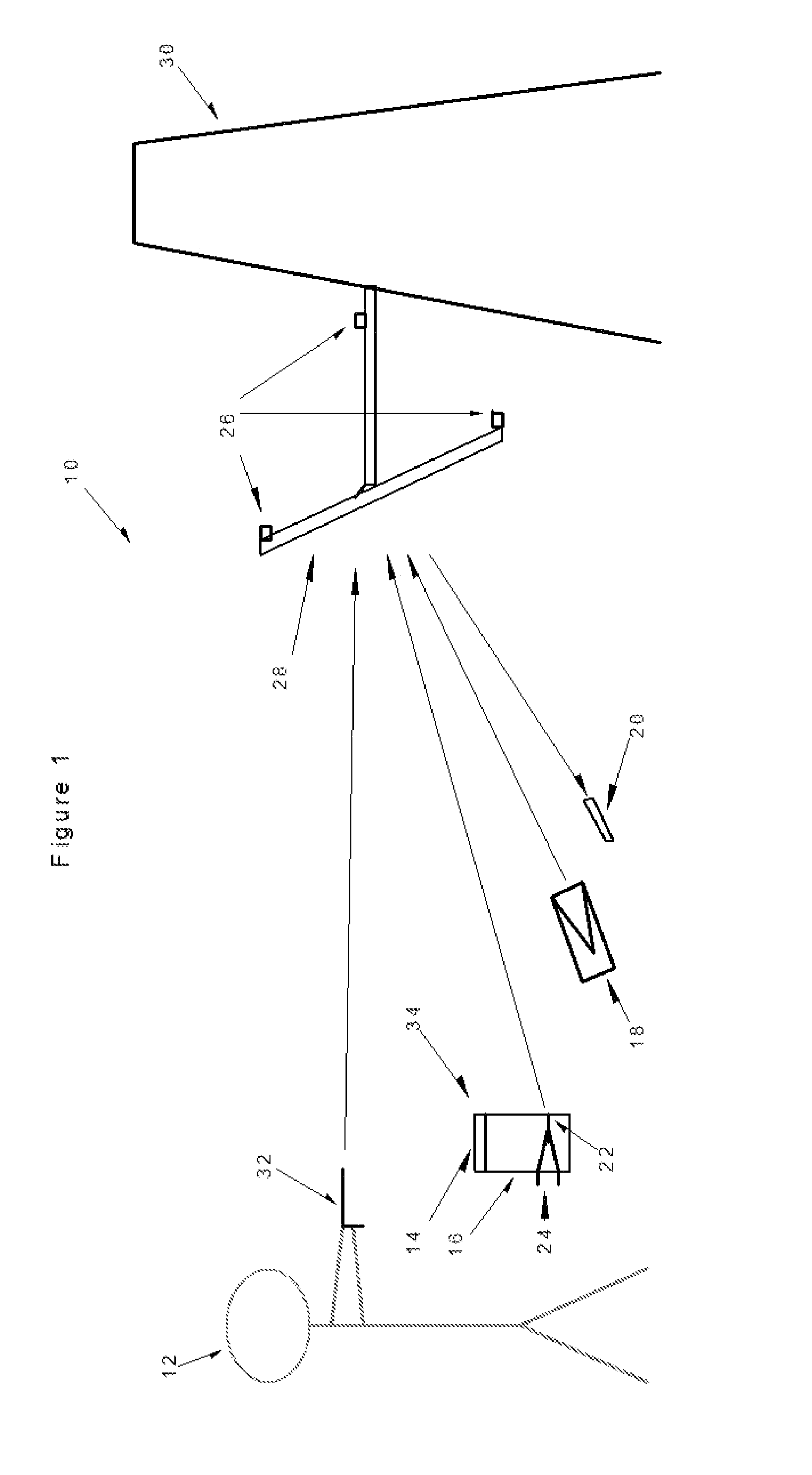
[0036]The apparatus described provides for an integrated system 10 that may create various training scenarios. The system 10 may use a visual display to determine targeting, consisting of a control device which may be located at or near the shooter or trainer and one or more detection devices generally mounted on or near the targets. FIG. 1 shows a typical placement of a shooter 12, using the system 10, wherein the system 10 may include one or more apparatus components including a user display 14, a controller 16, a projector 18, a recording device such as a camera 20, a laser 22, a laser-adjust mechanism 24, and a power supply (e.g. portable battery or fixed power unit(s)), as well as one or more sensors 26 and one or more targets 28. The target(s) 28 and / or the sensor(s) 26 may be associated with a support 30, such as a backstop.

[0037]The system 10 may allow the use of one or more unmodified weapons 32 and standard ammunition for firearms and other projectile weapons. In the conte...


PUM


Abstract

This apparatus offers multiple training scenarios which designates the targets to be hit and evaluates response. The apparatus assists in the evaluation and training of a shooter using multiple scenarios, detection of target strikes, timing, accuracy, and threat assessment. The system may be used with unmodified weapons and may not require attachments to weapon or shooter. The light source(s) in this apparatus may include visible lasers, focused light emitters, video or image projectors. The shooter may use live ammunition, and the weapon may be fired and operated independently of the control system. Hit detection on the targets may use vibration, accelerometer, acoustic, optical or thermal sensors that respond to projectile strikes on the designated target(s). If the specific location of the strike on the target is desired, nested targets and multiple sensor triangulation calculations may be used. This system designates which targets to shoot, when to fire, and evaluates the results.

Description

[0001]This application claims priority to U.S. PROVISIONAL Application Ser. No. 62 / 079,839, filed Nov. 14, 2014, the disclosure of which is hereby incorporated by reference.TECHNICAL FIELD[0002]This invention generally relates to a system for projectile weapons training, and more particularly to a system for detecting impact of said projectile weapons.BACKGROUND OF THE INVENTION[0003]Projectile weapon training systems, such as weapon firing simulation systems, are generally used to provide weapon training to a trainee. Generally, the trainee is given a modified weapon including a laser light used to engage a target or simulation. The purpose is to allow the trainee to practice his or her targeting skills with the projectile weapon without discharging said weapon. While this may provide an element of safety to the training scenario, it does not provide a realistic experience for the trainee which replicates the use of an unmodified weapon. The trainee is therefore not able to replica...

Claims


Application Information

Patent Timeline
Patent Type & Authority Applications(United States)
IPC IPC(8): F41J5/04
CPCF41J5/04F41J5/02F41J5/041F41J5/044F41J5/056F41J5/10F41J5/14F41J9/14
Inventor BEINE, ROBERT LEONBEINE, ROBERT BARKSDALE
Owner LATTS LLC
Learn More