
Clothes dryer and control method thereof

Active Publication Date: 2016-05-19
SAMSUNG ELECTRONICS CO LTD
View PDF9 Cites 40 Cited by
  • Summary
  • Abstract
  • Description
  • Claims
  • Application Information

AI Technical Summary

Benefits of technology

The patent text describes a clothes dryer that can prevent the failure of the air flow caused by excessive air volume and the return of moisture from condensation. This allows the dryer to work more effectively even at increased air blowing levels.

Problems solved by technology

When the condensation water flows back into the air circulation passage, the condensation water may be dispersed to the clothes in a drum along with the air circulated by the air blowing device, and thus may disrupt a drying operation.
However, the condensation water may not be collected properly in the condensation water container due to a negative pressure, and the water level may not be normally detected by the water level sensor, and thus the pump may not be normally operated.
When the air volume is increased using the air blowing device generating the high air volume, the pressure in the air circulation passage located at an upstream side of the air blowing device is further lowered, and thus the backflow problem of the condensation water may worsen.
In this case, the same problem may occur.

Method used


Image

  • Clothes dryer and control method thereof
  • Clothes dryer and control method thereof
  • Clothes dryer and control method thereof

Examples


second exemplary embodiment

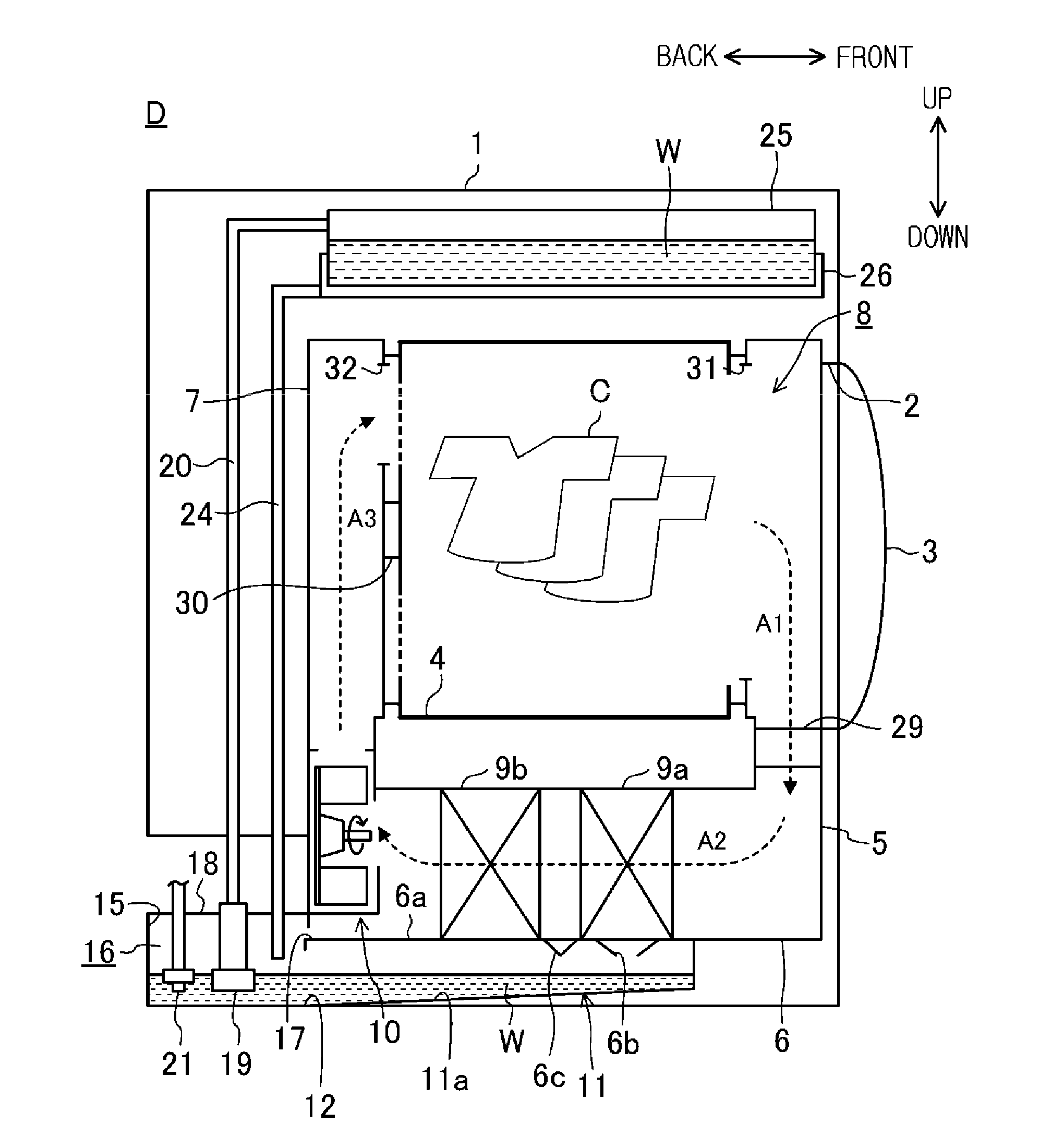
[0136]FIG. 13 is a view illustrating a clothes dryer D according to a second exemplary embodiment. The clothes dryer D of FIG. 13 is different from that of FIG. 2 in that a check valve 41 which prevents the air from being introduced from the water storage tank 25 toward the pump 19 is disposed at the lift hose 20 connecting the pump 19 with the water storage tank 25. Due to the check valve 41, the air in the pump casing 19b may be prevented from being introduced from the water storage tank 25 through the discharge port 19f of the pump 19, and also from being collected around the impeller 19e and forming bubbles. That is, the condensation water W may be normally discharged by the pump 19.

third exemplary embodiment

[0137]FIG. 14 is a view illustrating a clothes dryer D according to a third exemplary embodiment. The clothes dryer D of FIG. 14 is different from that of FIG. 2 in that the impeller 19e and the suction port 19a of the pump casing 19b are disposed to be inclined with respect to a horizontal plane. Specifically, as illustrated in FIG. 15, the motor 19d, the shaft 19c and the impeller 19e of the pump 19, a part of the pump casing 19b accommodating them, and the suction port 19a are disposed to be inclined with respect to the horizontal plane, such that the discharge port 19f is disposed higher.

[0138]Due to such a structure, even when the air is introduced (flows back) from the water storage tank 25 into the pump casing 19b through the discharge port 19f, the air is discharged from an upper end side of the suction port 19a which is inclined as indicated by an arrow A11 in FIG. 15, and thus the air is not collected around the impeller 19e, and the impeller 19e may be submerged. That is,...

fourth exemplary embodiment

[0140]FIG. 16 is a view illustrating a clothes dryer D according to a fourth exemplary embodiment. The clothes dryer D of FIG. 16 is different from that of FIG. 2 in that a third ventilation hole 51 passing through an upper plate 6i of the drying duct 6 in the vertical direction is installed between the evaporator 9b and the air blowing device 10 so that the air circulation passage 8 is in communication with an internal space of the clothes dryer D. Also, the clothes dryer D according to the exemplary embodiment includes an opening and closing valve 52 which opens and closes the third ventilation hole 51 depending on certain conditions. The opening and closing valve 52 may be controlled by the control unit 14.

[0141]Depending on the certain conditions, the opening and closing valve 52 closes the third ventilation hole 51, for example, at an early stage of the drying operation (in which the condensation water is hardly generated), and opens the third ventilation hole 51, when the cond...


PUM


Abstract

Provided is a clothes dryer including: a drum; an air circulation passage connected to the drum; a cooling device configured to cool and dehumidify air; a heating device configured to heat the air; an air blowing device configured to circulate air; a base plate configured to collect condensation water generated from the cooling device; a pump chamber accommodating a pump; a water circulation passage connecting the base plate to communicate with the pump chamber; a communication passage provided between the air circulation passage and the base plate and configured to guide the condensation water generated at the cooling device to the base plate; a first ventilation hole configured to provide a first air passage between the air circulation passage and the pump chamber; and a second ventilation hole configured to provide a second air passage between the air circulation passage and the base plate.

Description

CROSS-REFERENCE TO RELATED APPLICATION[0001]This application claims priority from Korean Patent Application No. 10-2015-0055135, filed on Apr. 20, 2015 in the Korean Intellectual Property Office and JP2014-234346, filed on Nov. 19, 2014 in the Japan Patent Office, the disclosure of which are incorporated herein by reference in their entireties.BACKGROUND[0002]1. Field[0003]Methods and apparatuses consistent with exemplary embodiments relate to a clothes dryer (or a laundry dryer) and a control method thereof.[0004]2. Description of the Related Art[0005]As one type of a clothes dryer, there is a circulation type clothes dryer in which air dehumidified and heated by a heat exchanger is circulated to dry clothes.[0006]The circulation type clothes dryer includes a cooling device which cools and dehumidifies circulation air, a heating device which heats the air dehumidified by passing through the cooling device, an air blowing device which circulates the air, and an air circulation passa...

Claims


Application Information

Patent Timeline
IPC IPC(8): D06F58/24D06F58/28D06F58/26
CPCD06F58/24D06F2058/2864D06F58/28D06F58/26D06F58/206D06F58/38D06F2103/08D06F2103/36D06F2105/24D06F2103/38D06F58/20D06F2103/58D06F2105/30D06F2105/36D06F2105/62D06F2103/42
Inventor KITAYAMA, NAOKIWAKIZAKA, EIJI
Owner SAMSUNG ELECTRONICS CO LTD
Learn More