Eureka AIR delivers breakthrough ideas for toughest innovation challenges, trusted by R&D personnel around the world.

Mooring system and drill ship including the same

Active Publication Date: 2016-05-19
SAMSUNG HEAVY IND CO LTD
View PDF7 Cites 0 Cited by
  • Summary
  • Abstract
  • Description
  • Claims
  • Application Information

AI Technical Summary

Benefits of technology

The present invention provides a drill ship with a guide groove on the bottom of its hull, which allows for efficient mooring to adapt to environmental loads. The guide groove can have a different shape than the shape of the moon pool, which can have various cross-sectional shapes. The technical effect is an improved and flexible mooring system for drill ship operations.

Problems solved by technology

However, when fixed-type crude oil and natural gas drill equipment is installed in a polar region, such as the Arctic Ocean, there is a problem in that the fixed-type drill apparatus is damaged due to collision with an ice floe or a support unit of the fixed-type drill equipment buckles due to an increase in ice load caused by freezing seawater in a winter season.
Therefore, it is not desirable to use the fixed-type drill apparatus in the polar region.
Also, since it is uneconomical to install the fixed-type drill apparatus in a small-scale offshore oil well that has a small amount of crude oil to be mined from one borehole, use of a floating drill equipment, such a as drill ship equipped with a drill apparatus, has significantly increased.
However, the drill ship is floating equipment, and as such it is hard for the drill ship to remain at rest at a certain position due to an environmental load caused by wind, waves, and tidal currents.
That is, when the drill ship is shaken, fatigue corrosion of the drill ship and the like caused by the environmental load is generated.
When the fatigue corrosion is generated, transgranula corrosion breaking gradually proceeds, thereby a service life of the drill ship is reduced.

Method used


Image

  • Mooring system and drill ship including the same
  • Mooring system and drill ship including the same
  • Mooring system and drill ship including the same

Examples


Embodiment Construction

[0022]As embodiments allows for various changes and numerous embodiments, exemplary embodiments will be illustrated in the drawings and described in detail in the written description. However, this is not intended to limit embodiments to particular modes of practice, and it is to be appreciated that all changes, equivalents, and substitutes that do not depart from the spirit and technical scope of embodiments are encompassed in embodiments. In the description of embodiments, certain detailed explanations of the related art are omitted when it is deemed that they may unnecessarily obscure the essence of the inventive concept.

[0023]Hereinafter, embodiments of the present invention will be described with reference to the accompanying drawings, but the same or like reference numerals designate the same components and overlapping descriptions thereof will be omitted.

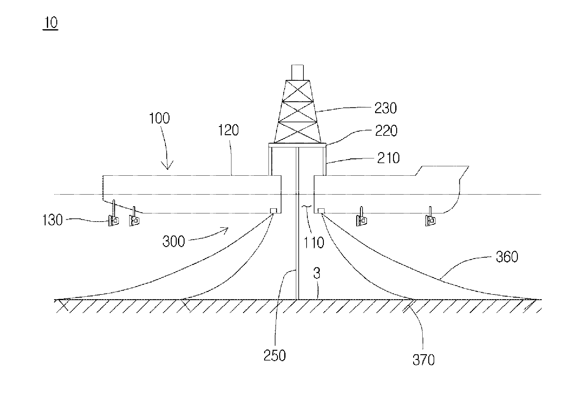
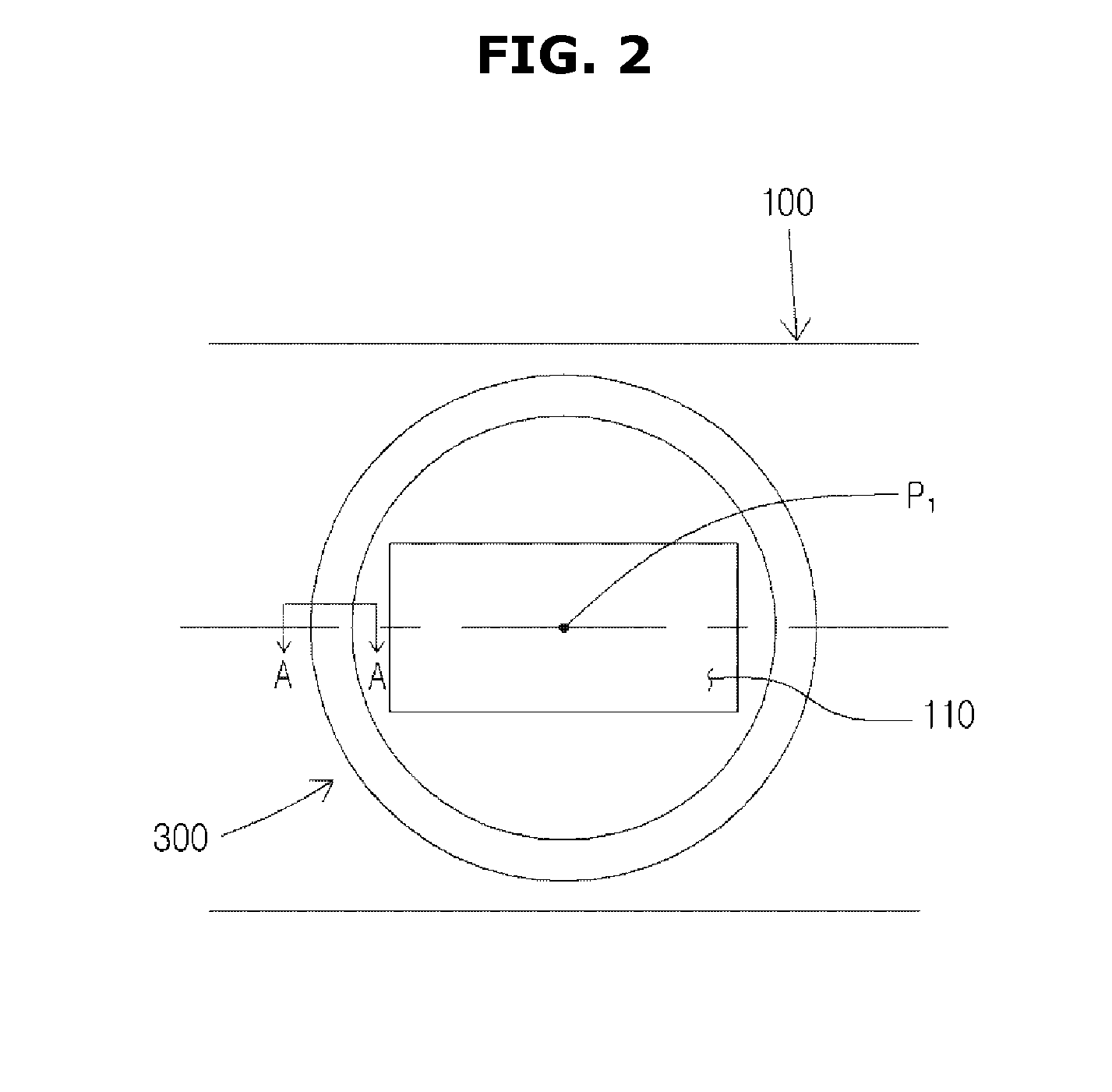
[0024]FIG. 1 is a side view of a drill ship according to an embodiment of the present invention, FIG. 2 is a bottom view of...


PUM


Abstract

Disclosed are a mooring system and a drill ship including the same. The mooring system according to an embodiment of the present invention includes a circular guide groove formed on a bottom surface of a hull and configured to use a center of the moon pool as a center thereof, a turret having a ring shape and inserted into the guide groove to rotate, and a bearing interposed between the turret and the guide groove to rotate with respect to the guide groove of the turret.

Description

TECHNICAL FIELD[0001]The present invention relates to a mooring system and a drill ship including the same.BACKGROUND ART[0002]Recently, there is a move to actively drill and explore the Arctic Ocean in which a large amount of crude oil is buried. However, when fixed-type crude oil and natural gas drill equipment is installed in a polar region, such as the Arctic Ocean, there is a problem in that the fixed-type drill apparatus is damaged due to collision with an ice floe or a support unit of the fixed-type drill equipment buckles due to an increase in ice load caused by freezing seawater in a winter season. Therefore, it is not desirable to use the fixed-type drill apparatus in the polar region.[0003]Also, since it is uneconomical to install the fixed-type drill apparatus in a small-scale offshore oil well that has a small amount of crude oil to be mined from one borehole, use of a floating drill equipment, such a as drill ship equipped with a drill apparatus, has significantly incr...

Claims


Application Information

Patent Timeline
IPC IPC(8): B63B21/50B63B3/14B63B35/44
CPCB63B21/507B63B2003/147B63B3/14B63B35/44B63B21/50
Inventor YUCK, RAE-HYOUNGCHOI, YONG-HOJUNG, DONG-WOO
Owner SAMSUNG HEAVY IND CO LTD
Why Eureka
Eureka Blog
Learn More