
Collimator for flow pixel proton therapy

Active Publication Date: 2016-05-19
THE CATHOLIC UNIV OF KOREA IND ACADEMIC COOPERATION FOUND
View PDF2 Cites 14 Cited by
  • Summary
  • Abstract
  • Description
  • Claims
  • Application Information

AI Technical Summary

Benefits of technology

The present invention provides a collimator for flow pixel proton therapy that can be operated in a reverse collimation mode, allowing for real-time corrections and adapting to the treatment schedule. This results in cost savings, reduced delay in treatment, and improved efficiency of the collimator. The collimator can also be mechanically designed in a simple and efficient manner over the hardware used for traditional damper and compensator.

Problems solved by technology

The said traditional multi-leaf collimator is necessarily attached to and used in almost all radiotherapy instruments in a radiation therapy at present, but there is an inconvenience that a plurality of leafs(leaf) are operated by seperately and directly moving.
In addition, the said multi-leaf collimator is expensive as an imported article, is dificult to be self-produced, and when it is attached to and used in the radiation therapy, a plurality of leafs(leaf) maintain the space form by moving them every movement, but they do not change their position, only except for changing the said space form in place.
Therefore, it is ungent to introduce the technology into Korea, which can display a high performance per price in a formation of a complex dose region, or a control of a short or irregular dose intensity, as an instrument which can be manufactured by only Korean technology, and display the same degree of performance at a very lower price than the multi-leaf collimator.
But, since such the compensator is patient-specific, it should be individually produced for each patient, and cannot be reused in other patient after the treatment, as well as even in the same patent, when the beam direction used in the treatment is increased, the same number of compensators should be produced.
Therefore, the continuously high expenditure for the material cost is occured, and since the time required for manufacturing the compensator is too long, there are problems in treating many patients at the same time or in rapidly treating the emergency patient.
In addition, when two or more of beams are used, there is a risk that a treatment is to be made while reversing compensators each other by a human error.
As mentioned above, since the proton therapy should produce and use high energy protons, it cannot be used in a hospital equiping with a seperate production facility.
Although the problem of delaying is a part being resolved by the normal effort, there is an inconvience that all damping materials suitable for tumor tissues should be produced in each patient.

Method used


Image

  • Collimator for flow pixel proton therapy
  • Collimator for flow pixel proton therapy
  • Collimator for flow pixel proton therapy

Examples


Embodiment Construction

[0038]The followings will explain the use state of the collimator for flow pixel proton therapy together with the movement of the spread panel for composing the proton irradiation region.

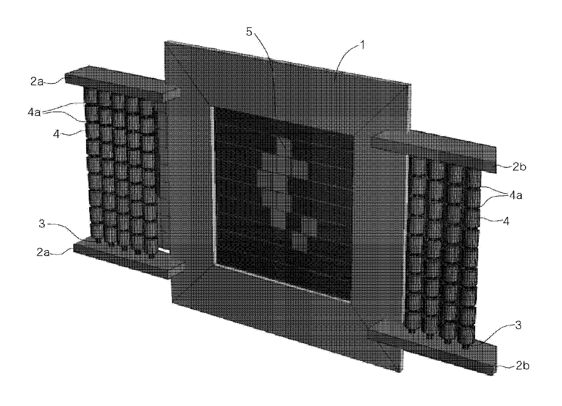
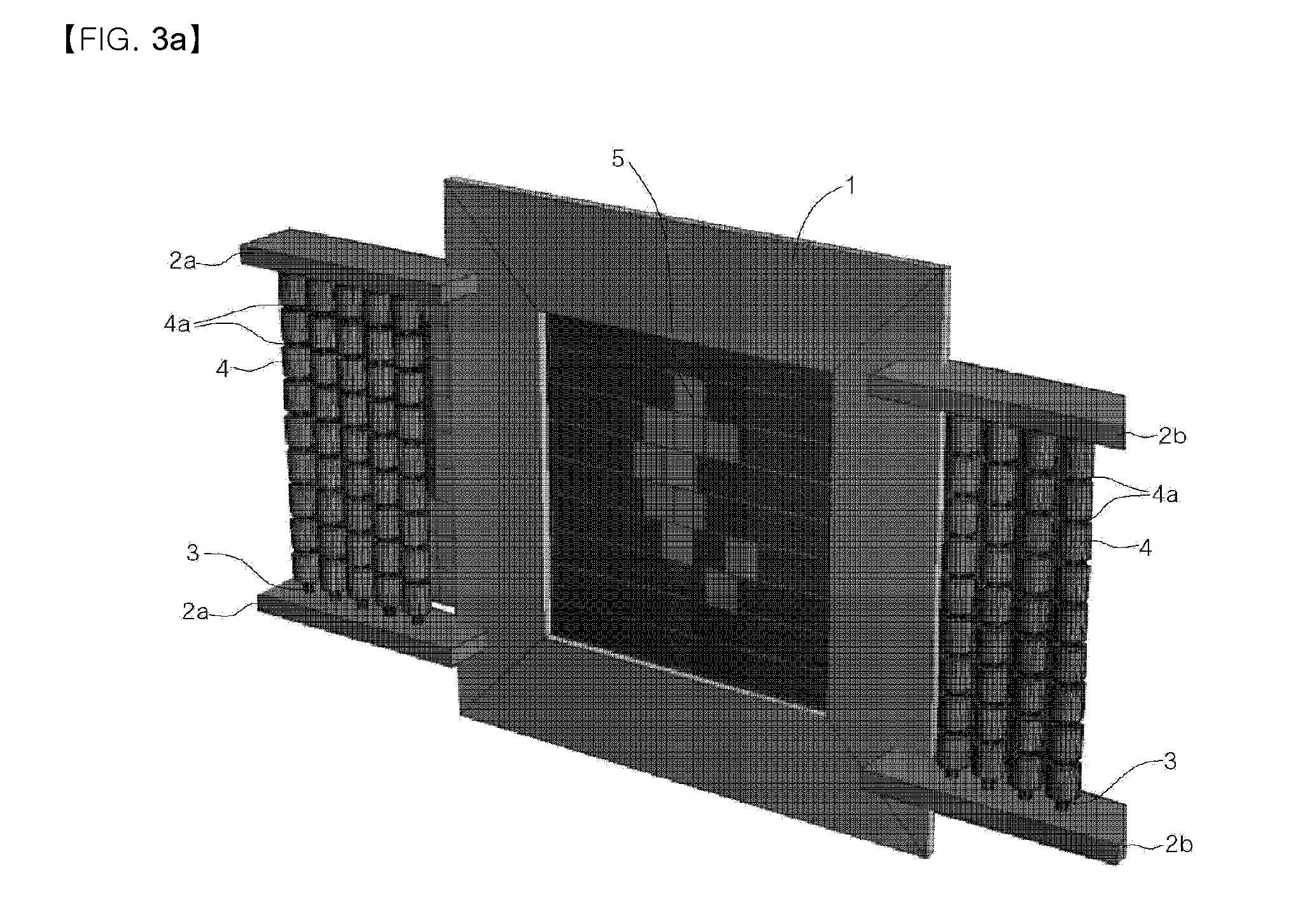
[0039]FIG. 3a is the front perspective view of the collimator for flow pixel proton therapy of the present invention composing the irradiation region for the proton therapy in some of the center by moving some of the spread panels to both sides, FIG. 3b depicts the behind perspective view of the collimator for flow pixel proton therapy of the present invention composing the irradiation region for the proton therapy in some of the center by moving some of the spread panel to both sides.

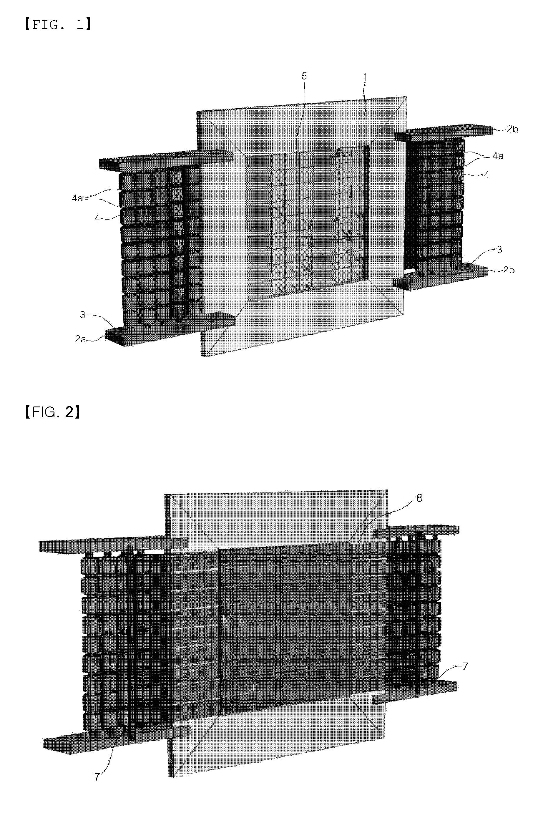
[0040]The collimator for flow pixel proton therapy of the present invention composes the irradiation region of the proton by moving the relevant spread panel 5 with selectively winding or unwinding the elastic reel 6 by the driving of the micro-motor 4 according to the control of the controller.

[0041]That is, as depict...


PUM


Abstract

The present invention relates to a collimator for flow pixel proton therapy, comprising an irradiation region for controlling the intensity of protons to be irradiated by directing shapes of various spaces, wherein a plurality of micro-motors arranged at both sides and a plurality of spread panels arranged in the center are connected to each other, one to one, by an elastic reel, relatively far micro-motors and spread panels are connected to each other by a ratio of the same number, and the plurality of spread panels arranged in the center, which are divided in half and moved to both sides by the opposite micro-motors, are allowed, by the micro-motors, to be in a stress release state of being unwound by the elastic reel. A method for manufacturing a damper and a compensator for proton therapy, which have been conventionally manufactured by hand, is provided to use reverse collimation through a collimator, thereby collimating spread panels at a section requiring spread at the Bragg peak, determining the shape of the section and a damping section through a program, and applying the same to tumor treatment.

Description

TECHNICAL FIELD[0001]The present invention relates to a collimator for flow pixel proton therapy, specifically, to a collimator for flow pixel proton therapy, which is manufactured to allow the proton be correctly irradiated only on a tumor to be treated by arranging a plurality of spread panels in the form of pixel in the opened center of the main frame which becomes a proton irradiation region, arranging a plurality of micro-motors connected to each of the spread panel by an elastic reel, one to one, based on the far side to each other in both sides of said main frame, selectively moving each of the spread panels in or out of irradiation region of the radiation through the elastic reel with driving of each of micro-motors by a controller to allow the proton be correctly irradiated only on a tumor to be treated.BACKGROUND ART[0002]There is a need for controlling a dose of irradiation in a radiotherapy such as X-ray or gamma-ray and thus, a so-called collimator(collimator) is used. ...

Claims


Application Information

Patent Timeline
IPC IPC(8): A61N5/10G21K1/04
CPCA61N5/1045A61N2005/1087G21K1/046A61N5/10G21K1/02
Inventor JUNG, JOO YOUNGYOON, DO KUNSUH, TAE SUK
Owner THE CATHOLIC UNIV OF KOREA IND ACADEMIC COOPERATION FOUND
Learn More