
Multifunction light-emitting diode lighting apparatus

a light-emitting diode and lighting apparatus technology, applied in lighting and heating apparatus, domestic cooling apparatus, light source combinations, etc., can solve the problems of uv sterilization efficiency degradation, reduced volume within the sterilization device, and reduced product volume, so as to improve the structure of the lighting apparatus, increase the internal volume of the product, and improve the effect of lighting apparatus

Active Publication Date: 2016-05-19
SEOUL VIOSYS CO LTD
View PDF7 Cites 33 Cited by
  • Summary
  • Abstract
  • Description
  • Claims
  • Application Information

AI Technical Summary

Benefits of technology

The present invention is a multifunction LED lighting apparatus that improves upon existing lighting products by incorporating sterilization and deodorization functions. The apparatus achieves these improvements through an improved structural design that increases the internal volume of the product it is mounted on. Additionally, the apparatus may provide a direct sterilization function or a combination of direct sterilization and sterilization and deodorization functions using a photocatalyst. Overall, the improvements provide enhanced cleaning and deodorization capabilities for indoor environments and combine the benefits of a lighting product with advanced sterilization and deodorization functions.

Problems solved by technology

However, the product using the conventional UV LED is disadvantageous in that volume within the product is reduced because the product must be designed to provide an additional space within the product in order to install the UV LED.
In such a case, a sterilization device using a conventional UV LED has a disadvantage in that volume within the sterilization device is reduced because an additional space on which electrical and electronic devices are mounted needs to be provided.
Furthermore, a sterilization device using a conventional UV LED has a disadvantage in that UV sterilization efficiency is deteriorated because a component that deteriorates UV light transmittance is added between a UV light source and a subject for pho-tography in order to protect the UV light source or improve an external appearance of the sterilization device.

Method used


Image

  • Multifunction light-emitting diode lighting apparatus
  • Multifunction light-emitting diode lighting apparatus
  • Multifunction light-emitting diode lighting apparatus

Examples


Embodiment Construction

[0044]Terms or words used hereinafter should not be construed as having common or dictionary meanings, but should be construed as having meanings and concepts that comply with the technical spirit of the present invention on the basis of the principle that the inventor may appropriately define the concepts of the terms in order to best describe his or her invention. Accordingly, the following description and drawings illustrate exemplary embodiments of the present invention and do not fully represent the scope of the present invention. It would be understood by one of ordinary skill in the art that a variety of equivalents and modifications of the embodiments exist.

[0045]Terms used herein are used to describe specific embodiments and are not intended to limit the present invention. An expression of the singular number used in this specification may include an expression of the plural number unless clearly defined otherwise in the context.

[0046]FIG. 1 is a schematic block diagram of ...


PUM

PropertyMeasurementUnit
wavelengthaaaaaaaaaa

Abstract

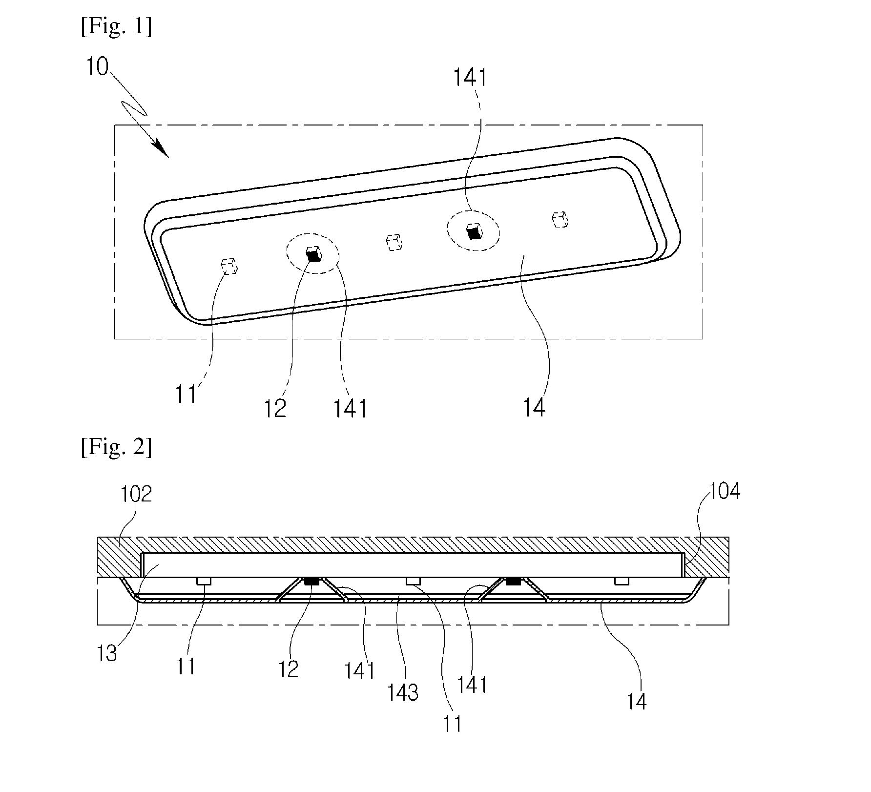
The multifunction LED lighting apparatus of the present invention includes a least one lighting LED, at least one ultraviolet (UV) LED, a substrate configured to have the at least one lighting LED and the at least one UV LED mounted thereon, and a cover disposed to face the substrate at a specific interval and configured to cover the lighting LED and the UV LED. The at least one lighting LED and the at least one UV LED are integrally mounted on the substrate and configured to form a single module of a thin sheet form, and the cover is installed to cover and support the single module placed on the inside wall of an application.

Description

TECHNICAL FIELD[0001]The present invention relates to a multifunction Light-Emitting Diode (LED) lighting apparatus, and more particularly, to a multifunction LED lighting apparatus which is capable of increasing the internal volume of an application on which the lighting apparatus is mounted by improving a structure in which a lighting apparatus having a sterilization and deodorization function is installed and of providing a high sterilization and deodorization function as an indoor lighting apparatus.BACKGROUND ART[0002]An LED is used as lighting means or display means that replaces an existing electric bulb because it have some advantages in that the size is small, consumption power versus brightness is high, lifespan is long, and a manufacturing cost is low.[0003]An LED may be classified into an infrared LED that emits infrared rays, a visible ray LED that emits a visible ray, and an ultraviolet (UV) LED that emits ultraviolet rays depending on emission characteristics. After a...

Claims


Application Information

Patent Timeline
Patent Type & Authority Applications(United States)
IPC IPC(8): A61L2/10A61L9/20F21V23/04F21V23/00F21V33/00F21V3/04
CPCA61L2/10F21V33/0044F21V3/0409F21V33/0064F21Y2113/005F21V23/003A61L9/20F21W2131/305F21Y2101/02F21V23/04F25D27/00F21Y2115/10F21Y2113/13F21V3/06A61L9/00F21V17/00
Inventor PARK, JUNG YOULKIM, JONG RACKSON, YOUNG HWANLEE, SEONG MINYI, JAE SEON
Owner SEOUL VIOSYS CO LTD
Learn More