
Ambient water condensing apparatus

a condensing apparatus and ambient technology, applied in lighting and heating apparatus, refrigerating machines, machines using electric/magnetic effects, etc., can solve the problems of energy consumption and cos

Active Publication Date: 2016-05-12
EXAERIS WATER INNOVATIONS LLC
View PDF6 Cites 28 Cited by
  • Summary
  • Abstract
  • Description
  • Claims
  • Application Information

AI Technical Summary

Benefits of technology

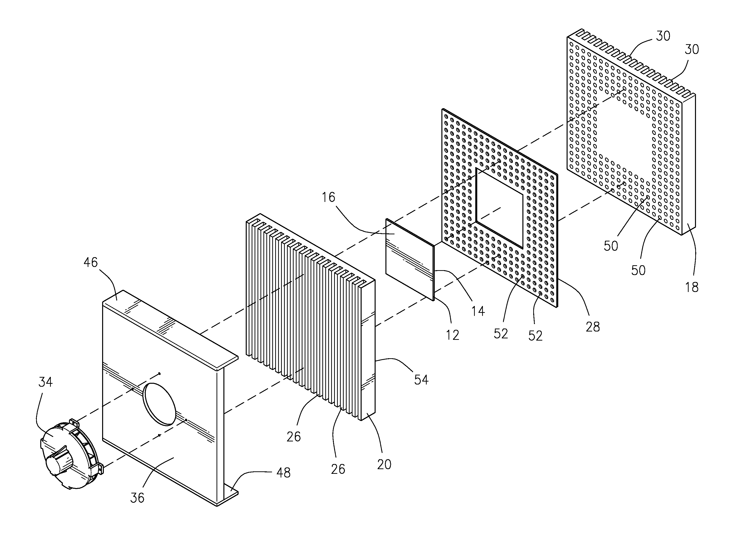
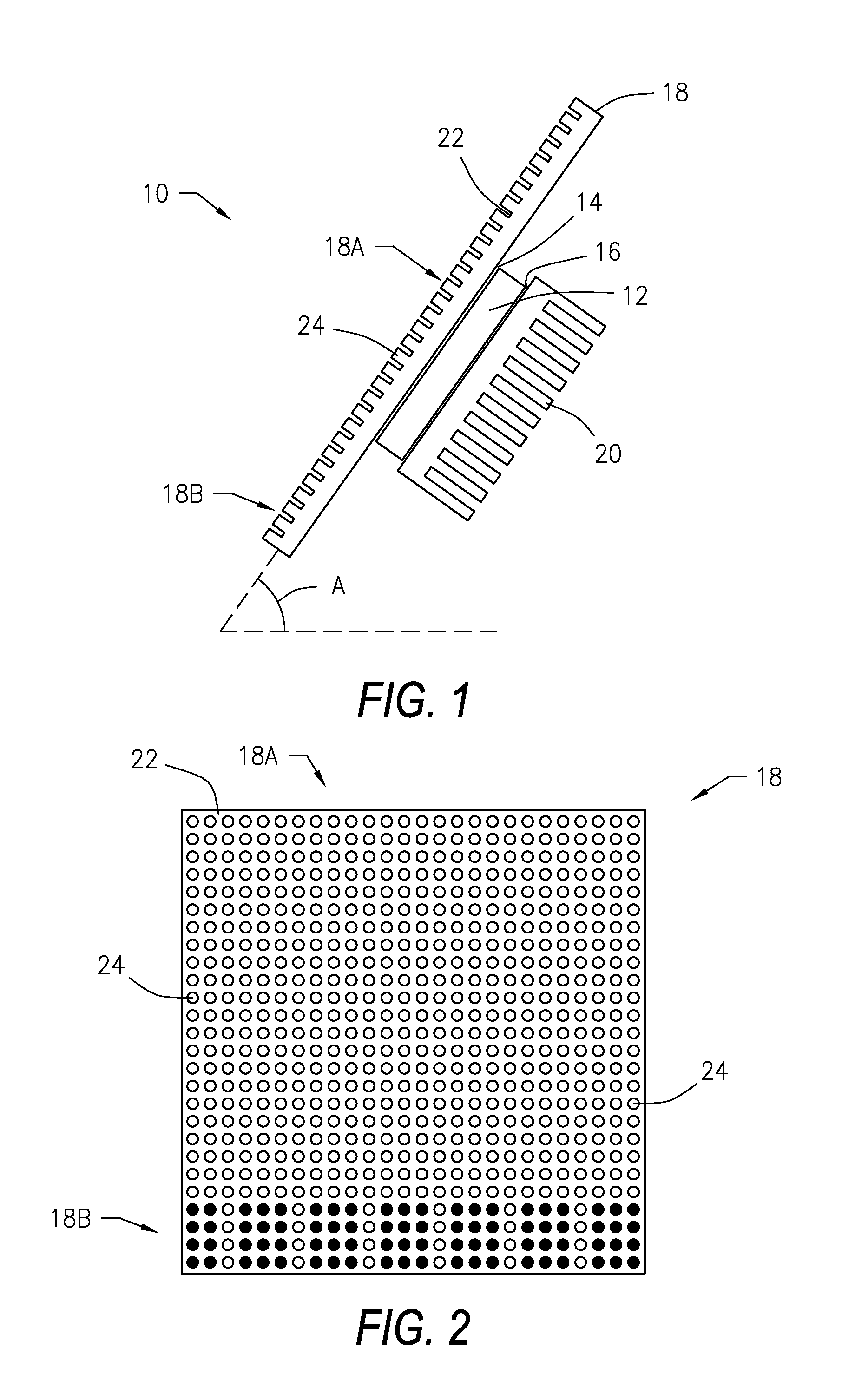
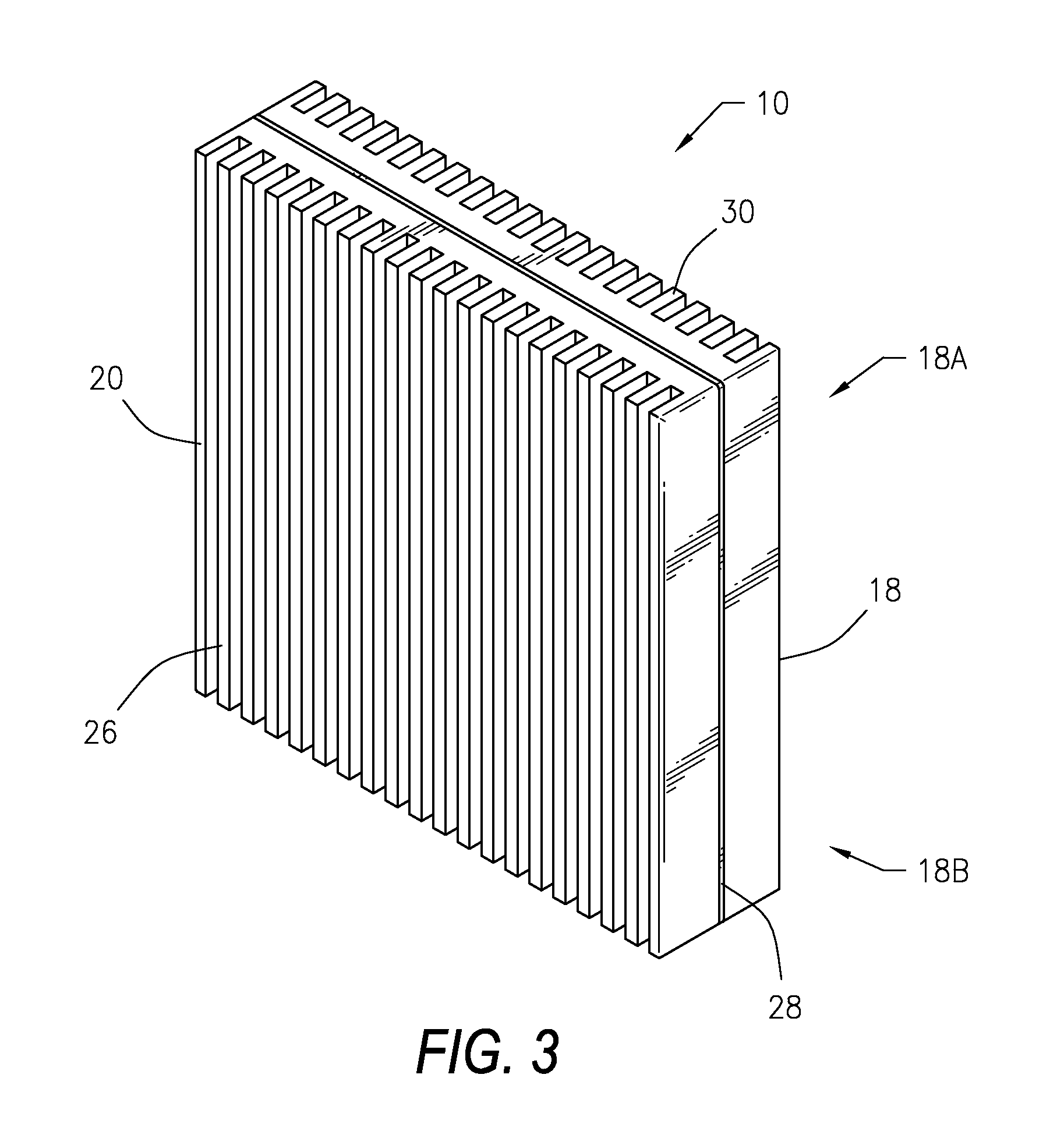
The invention relates to an ambient water condensing apparatus that uses a thermoelectric device to cool down air through a porous heat sink and a porous superhydrophobic condensing surface. The apparatus includes a fan element and an insulating material with protruding fin-like surfaces. The condensing surface can be a combination of superhydrophobic and superhydrophilic surfaces. The apparatus can also have axially aligned apertures and a heat sink cover or plate to direct the flow of air. The technical effects of the invention include improved cooling efficiency, reduced noise, and improved air quality.

Problems solved by technology

Generally, transporting water from groundwater sources to where the water is needed involves the installation of pipelines, pumps and water distribution means, all of which require energy and incur costs.

Method used


Image

  • Ambient water condensing apparatus
  • Ambient water condensing apparatus
  • Ambient water condensing apparatus

Examples


Embodiment Construction

[0036]The apparatuses and methods discussed herein are merely illustrative of specific manners in which to make and use this invention and are not to be interpreted as limiting in scope.

[0037]While the invention has been described with a certain degree of particularity, it is to be noted that many modifications may be made in the construction and the arrangement of the structural and function details disclosed herein without departing from the scope of the invention. It is understood that the invention is not limited to the embodiments set forth herein for purposes of exemplification.

[0038]The description of the invention is intended to be read in connection with the accompanying drawings, which are to be considered part of the entire written description of this invention. In the description, relative terms such as “front,”“rear,”“lower,”“upper,”“horizontal,”“vertical,”“above,”“below,”“up,”“down,”“top” and “bottom” as well as derivatives thereof (e.g., “horizontally,”“downwardly,”“u...


PUM


Abstract

An ambient water condensing apparatus that extracts water vapor from ambient air utilizing a thermoelectric device, a superhydrophobic and / or superhydrophilic radiating condensing surface and a heat sink for providing point of source irrigation or drinking water using conventional and / or sustainable energy supplies. The thermoelectric device is thermally coupled intermediate of the condensing surface and the heat sink, and in particular a cold side of the thermoelectric device is thermally connected to the condensing surface and a hot side of the thermoelectric device is thermally connected to the heat sink. The water condensing apparatus may also include at least one fan element that cools the heat sink and introduces additional air to the condensing surface. The thermoelectric device and the fan element may be powered by any suitable electrical energy source, such as by solar energy, wind energy or grid power.

Description

CROSS REFERENCE TO RELATED APPLICATIONS[0001]This application claims the benefit of and priority to U.S. Provisional Patent Application Serial No. 62 / 078,705, entitled HYBRID PASSIVE AND ACTIVE WATER COLLECTOR APPARATUS, filed Nov. 12, 2014, which is incorporated herein by reference in its entirety.STATEMENT REGARDING FEDERALLY SPONSORED RESEARCH OR DEVELOPMENT[0002]Not Applicable.NAMES OF THE PARTIES TO A JOINT RESEARCH AGREEMENT[0003]Not Applicable.REFERENCE TO A SEQUENCE LISTING, A TABLE, OR A COMPUTER PROGRAM LISTING APPENDIX[0004]Not Applicable.STATEMENT REGARDING PRIOR DISCLOSURES BY THE INVENTOR OR A JOINT INVENTOR[0005]Not Applicable.BACKGROUND OF THE INVENTION[0006]1. Field of the Invention[0007]This invention relates generally to an ambient water condensing apparatus, and more particularly to an ambient water condensing apparatus that extracts water vapor from ambient air utilizing a thermoelectric device, a superhydrophobic radiating condensing surface and a heat sink for...

Claims


Application Information

Patent Timeline
Patent Type & Authority Applications(United States)
IPC IPC(8): F25B21/04
CPCF25B21/04
Inventor OTANICAR, TODD P.STARKWEATHER, JARED
Owner EXAERIS WATER INNOVATIONS LLC
Learn More