Golf club head with adjustable center of gravity

a golf club head and center of gravity technology, applied in the field of golf club heads, can solve problems such as not optimizing weight adjustmen

Active Publication Date: 2016-05-12
TOPGOLF CALLAWAY BRANDS CORP
View PDF55 Cites 20 Cited by
  • Summary
  • Abstract
  • Description
  • Claims
  • Application Information

AI Technical Summary

Benefits of technology

[0011]Another aspect of the present invention is an iron-type golf club head comprising a body comprising a face, a top surface, a bottom surface, a hosel, a rear surface, a toe side, and a heel side, a pair of parallel rails, and a weight comprising a pair of grooves sized to receive the rails, wherein the pair of parallel rails is disposed on the rear surface. In some embodiments, the pair of parallel rails may extend from the heel side t

Problems solved by technology

The prior art includes several different solutions for adjustable

Method used


Image

  • Golf club head with adjustable center of gravity
  • Golf club head with adjustable center of gravity
  • Golf club head with adjustable center of gravity

Examples


Embodiment Construction

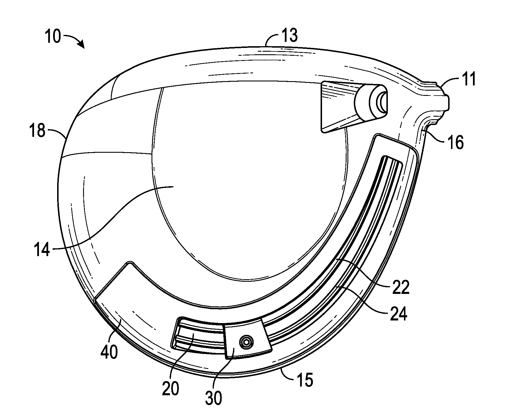
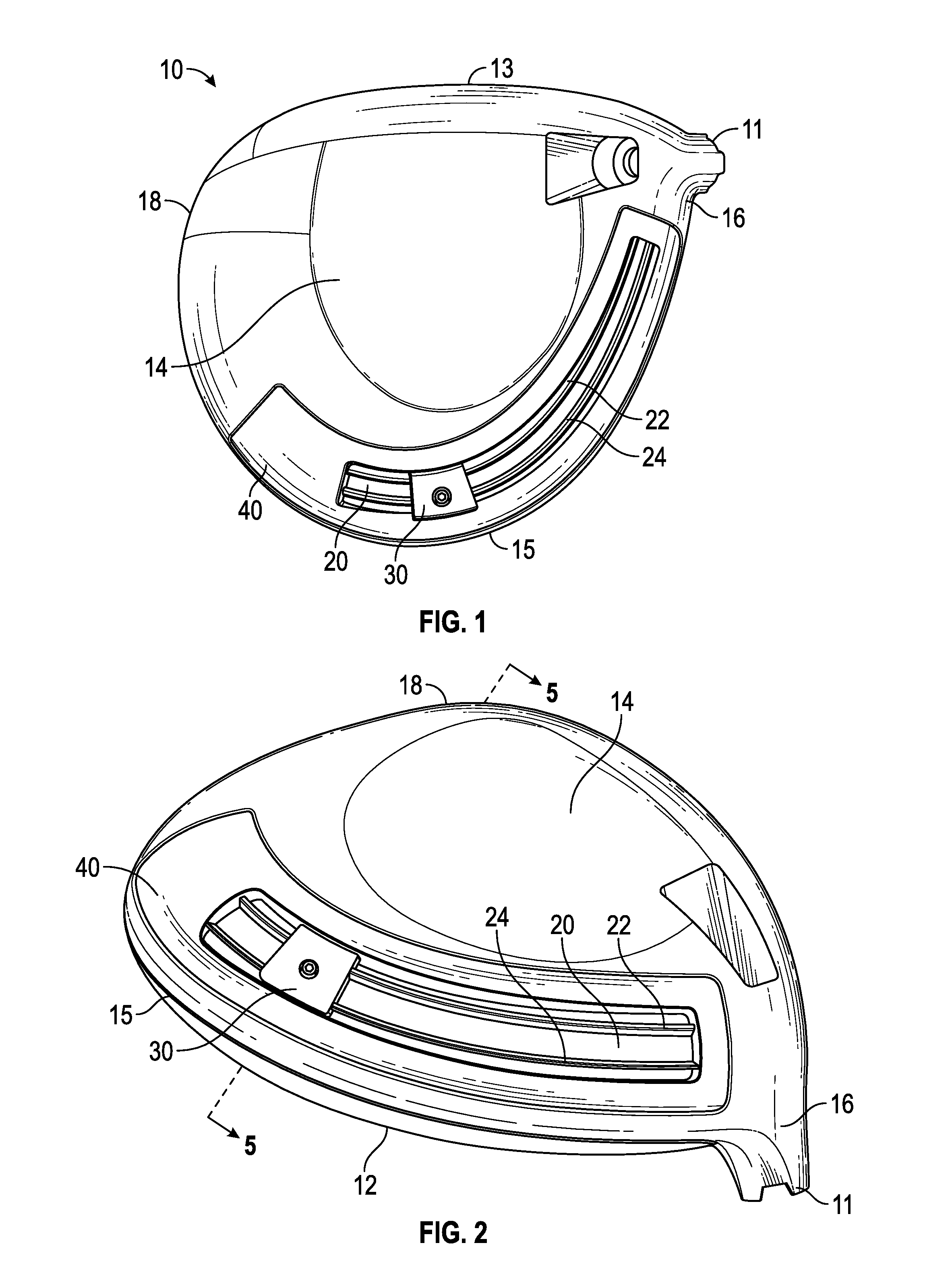
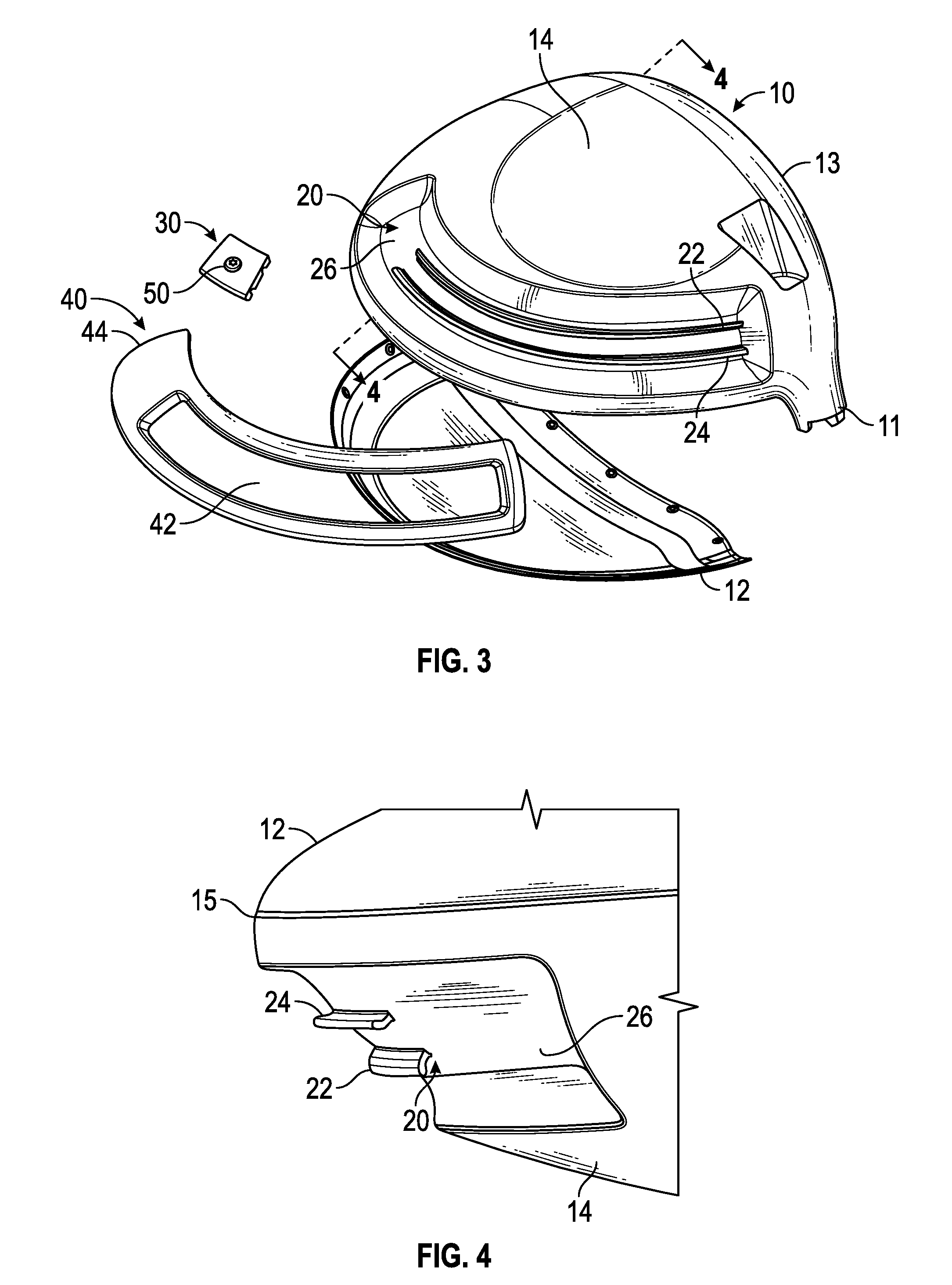
[0022]The design approaches described herein are based on a construction used in a driver head characterized by a composite crown adhesively bonded to a cast titanium body. This particular construction approach permits the crown configuration to be adapted to the inventive weighting scheme with minimal impact on weight and function. However, the weighting embodiments disclosed herein can be used with other constructions, including all titanium, all composite, and a composite body with metal face cup. The embodiments may also work in conjunction with at least one adjustable weight port on the club head. Shifting weight along the channel described herein allows for control of center of gravity location.

[0023]A first, preferred embodiment of the present invention is shown in FIGS. 1-5.

[0024]The golf club head 10, which preferably is a driver or a large fairway wood, comprises a channel 20 disposed within the sole 14 of the golf club head, though in alternative embodiments the channel 2...


PUM


Abstract

A golf club head comprising a slidable weight for adjusting the location of the golf club head center of gravity, as well as the golf club head bias, is disclosed herein. In particular, the golf club head, which may be a wood or iron-type head, comprises a pair of rails extending along at least one surface, such as a rear surface of an iron type head or a channel disposed in a wood-type head, and a slidable weight comprising a pair of grooves sized to receive the rails. In some embodiments, an applique or one or more clips are applied over or to the rails to prevent the weight from disengaging from the golf club head.

Description

CROSS REFERENCES TO RELATED APPLICATIONS[0001]The present application is a continuation of U.S. patent application Ser. No. 14 / 175,657, filed on Feb. 7, 2014, which claims priority to U.S. Provisional Patent Application Nos. 61 / 905,749, filed on Nov. 18, 2013, 61 / 898,956, filed on Nov. 1, 2013, and 61 / 893,728, filed on October 21, 2013, and is a continuation-in-part of U.S. patent application Ser. No. 14 / 174,068, filed on Feb. 6, 2014, which is a continuation-in-part of U.S. patent application Ser. No. 14 / 163,946, filed on Jan. 24, 2014, and issued on Dec. 15, 2015, as U.S. Pat. No. 9,211,453, which is a continuation-in-part of U.S. patent application Ser. No. 14 / 033,218, filed on Sep. 20, 2013, and issued on Apr. 15, 2014, as U.S. Pat. No. 8,696,491, which is a continuation-in-part of U.S. patent application Ser. No. 13 / 923,571, filed on Jun. 21, 2013, and issued on Jul. 21, 2015, as U.S. Pat. No. 9,084,921, which is a continuation-in-part of U.S. patent application Ser. No. 13 / 778...

Claims


Application Information

Patent Timeline
IPC IPC(8): A63B53/06A63B53/04
CPCA63B2053/0491A63B2053/0433A63B53/0466A63B53/06A63B53/0433
Inventor MYERS, MATTHEWHOLT, DENVERSELUGA, JAMES A.KIM, WEE JOUNGSUTTON, STEVEN C.
Owner TOPGOLF CALLAWAY BRANDS CORP
Why Eureka
Try Eureka